

Multi-stage distillation equipment
A distillation device and technology of all levels, applied in the direction of distillation separation, heating water/sewage treatment, energy wastewater treatment, etc., can solve the problems of high distillation cost, latent heat utilization and low distillation efficiency
- Summary
- Abstract
- Description
- Claims
- Application Information
AI Technical Summary
Problems solved by technology
Method used
Image

Examples
Embodiment 1
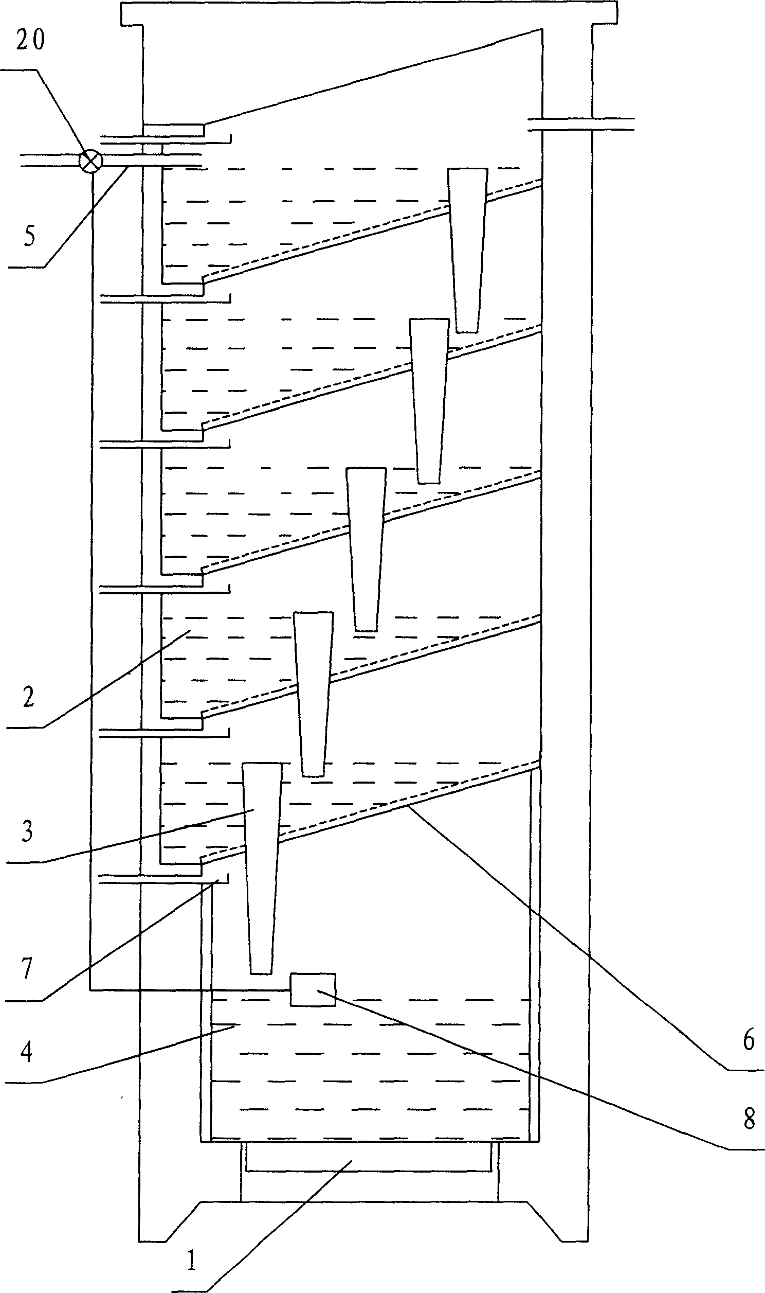
[0029] Embodiment 1: as figure 1The shown multi-stage distillation device includes: an electric heater 1, a five-stage condensation distillation vessel 2, an overflow pipe 3 and a distillation vessel 4 whose number matches the condensation distillation vessel 2. The electric heater 1 is connected to the distillation vessel 4, and each condensation distillation vessel 2 is stacked and combined, and placed on the distillation vessel 4; the distillation vessel 4 and each condensation distillation vessel 2 are connected to each other through the overflow pipe 3; 2 is provided with a water inlet pipe 5, and the distillation container 4 is provided with a float type water level control device 8 to control the switch of the electromagnetic valve 20 of the water inlet pipe 5, and the water level control device 8 and each overflow pipe 3 jointly control the water level in each container, That is, the necessary evaporation space is reserved on the top of the distillation vessel 4 and th...
Embodiment 2
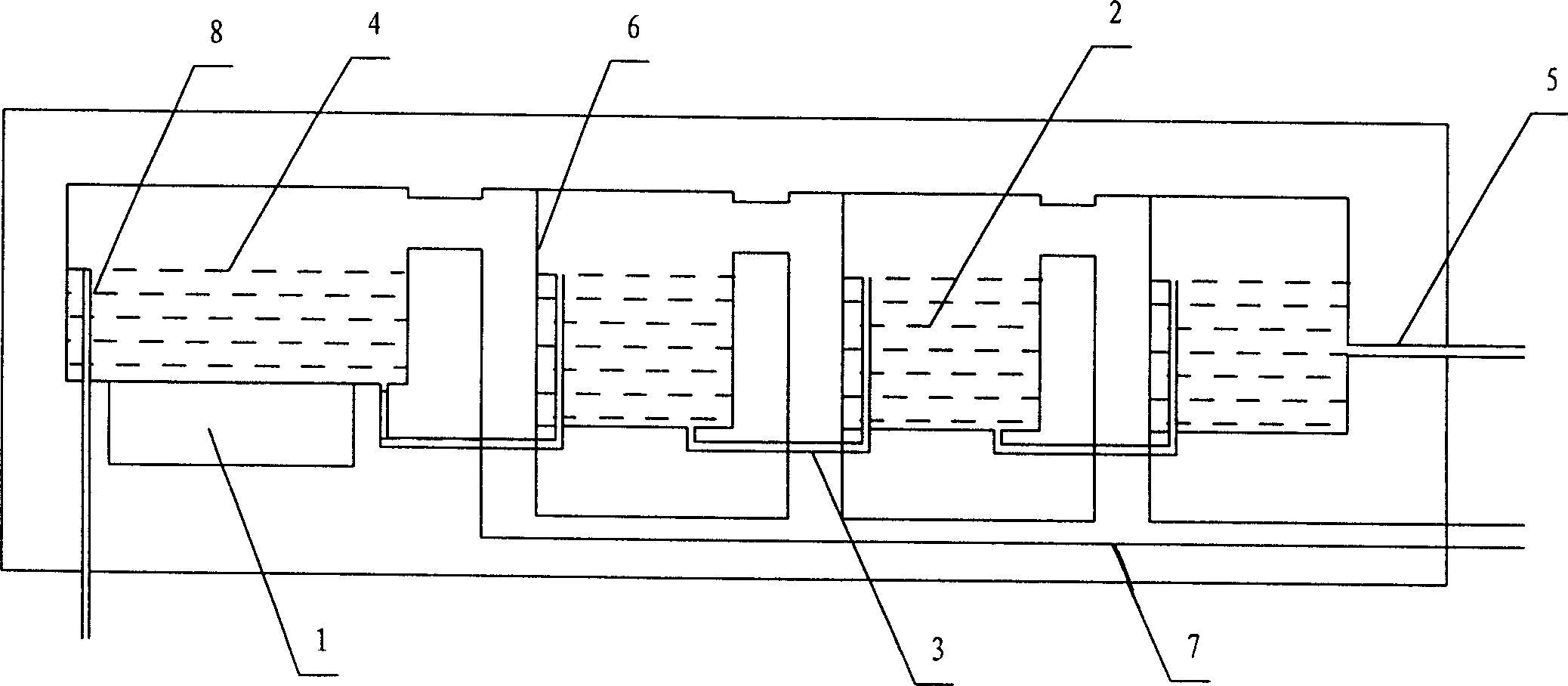
[0030] Embodiment 2: as image 3 As shown, it is basically the same as Embodiment 1, except that the heater 1 is connected with the distillation vessel 4, and each condensation distillation vessel 2 is combined side by side, and the distillation vessel 4 communicates with the condensation surface 6 of the primary condensation distillation vessel 2, and the distillation vessel 4 and each The condensing distillation vessels 2 communicate with each other through the overflow pipe 3; a water inlet pipe 5 is provided in the final condensing distillation vessel 2, and a water level control device 8 is provided in the distillation vessel 4, and the water level control device 8 and each overflow pipe 3 jointly control each container The water level in the interior, that is, the necessary evaporation space is reserved on the top of the distillation vessel 4 and the condensation distillation vessel 2; Below, be provided with the sump plate container 7 that matches it.
Embodiment 3
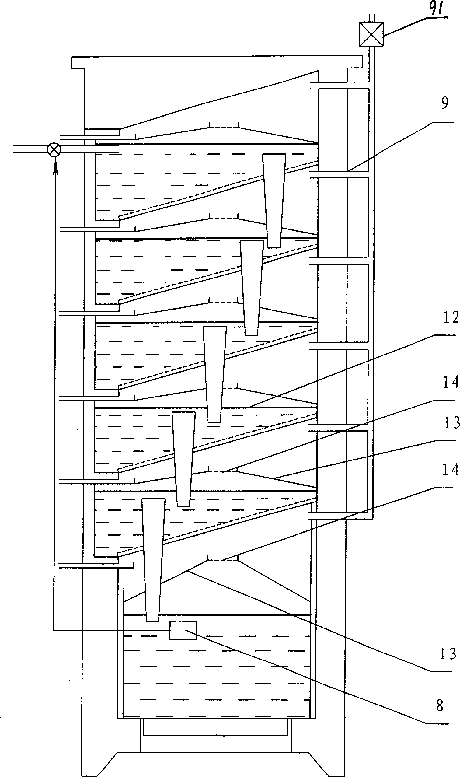
[0031] Embodiment 3: as figure 2 As shown, it is basically the same as Embodiment 1, the difference is that between the distillation vessel 4 and the primary condensation surface 6, and between the condensation distillation vessels 2 at all levels, heat shields 13 are respectively provided, and the heat shields 13 have energy-conducting The orifice 14 for flowing steam not only provides a channel for diverting steam, but also ensures the completion of distillation and condensation, and relies on the heat shield to block conduction heat and radiant heat, which can avoid the gap between the distillation vessel 4 and the primary condensation surface 6, and the The heat conduction and heat radiation between the condensing distillation vessels 2 weaken the heat energy attenuation degree of each stage and improve the distillation effect of each stage.
PUM
 Abstract
Description
Claims
Application Information