Experimental platform of parallel mechanism with 3 and 4 freedom and adjustable 3-UPU

An experimental platform, 3-UPU technology, applied in manipulators, program-controlled manipulators, metal processing machinery parts, etc., can solve the unexplainable self-motion phenomenon of three-translational 3-UPU mechanisms, single movement characteristics of parallel mechanisms, and unfavorable multiple structures Type parallel mechanism characteristics and kinematic characteristics and other issues

Inactive Publication Date: 2006-03-15
YANSHAN UNIV
View PDF1 Cites 28 Cited by
  • Summary
  • Abstract
  • Description
  • Claims
  • Application Information

AI Technical Summary

Problems solved by technology

At present, the poses and postures of the motion pairs of various parallel mechanisms with few degrees of freedom are not adjustable, so the kinematic characteristics of each parallel mechanism are single, which is not conducive to experimental research on the characteristics and kinematic characteristics of parallel mechanisms with multiple configurations.
The existing parallel mechanism theory cannot explain the self-motion phenomenon of the three-translational 3-UPU mechanism and other parallel mechanisms with few degrees of freedom, and it is necessary to carry out relevant theoretical and experimental research

Method used


Image

  • Experimental platform of parallel mechanism with 3 and 4 freedom and adjustable 3-UPU
  • Experimental platform of parallel mechanism with 3 and 4 freedom and adjustable 3-UPU
  • Experimental platform of parallel mechanism with 3 and 4 freedom and adjustable 3-UPU

Examples


Embodiment 1

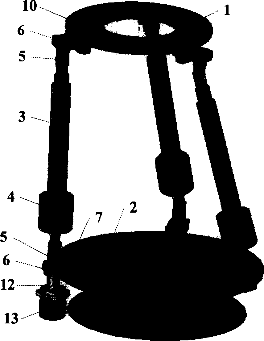
[0015] figure 1 It is the first embodiment disclosed by the present invention. The three linear drive branch kinematic chains have the same structure and are symmetrically distributed in an equilateral triangle. Each linear drive branch has a universal pair at both ends and a moving pair 3 in the middle. Overlap towards the center of the sub-center, and the moving sub-3 is driven by a stepping electromechanical drive device to realize telescopic movement. Each universal pair is composed of a rotating shaft 5, a bracket 6 and a fan seat 7, the bracket 6 is connected to the fan seat 7 at 0° by pins 8 and 9, and the fan seat 7 is connected to the upper platform by pins 10 and 11. 1 or the base 2 are connected at 0° for positioning and rotation, and each rotating shaft 5 connected with the upper platform 1 and the machine base 2 is kept perpendicular to the upper platform and the machine base respectively. At this time, the mechanism has 4 degrees of freedom, and the sleeve 12 Th...

Embodiment 2

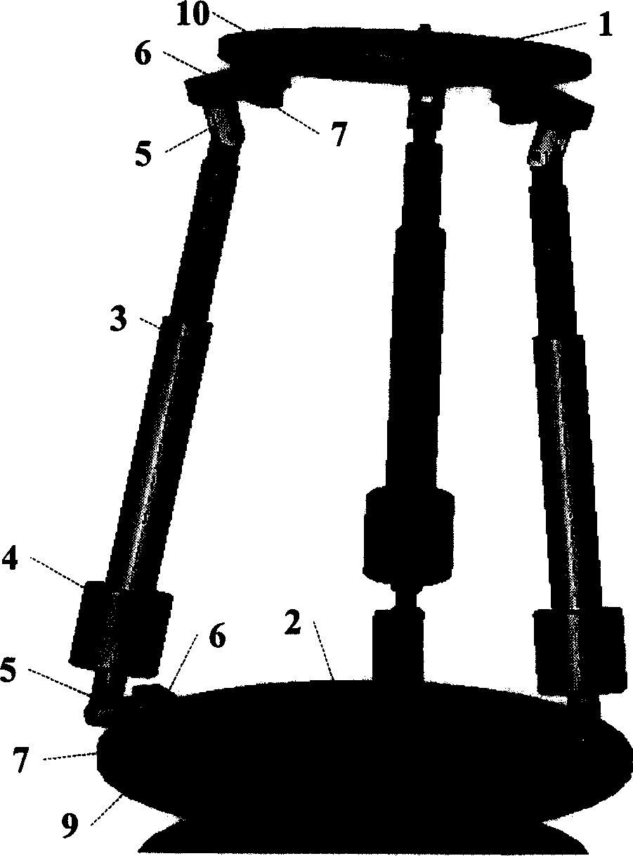
[0017] image 3 It is the second embodiment disclosed by the present invention. It differs from the first embodiment in that the bracket 6 on the upper platform 1 is connected with the fan seat 7 in a 45° rotational positioning by the pin 8 and the pin 9, and the pin 10 and pin 11 realize that the bracket 6 on the machine base 2 is connected with the fan base 7 in a 90° rotation orientation, and the fan base 7 is connected with the upper platform 1 or the base 2 in a 0° rotation orientation. This mechanism has 3 degrees of freedom.

[0018] There are 3 and 4 adjustable 3-UPU parallel mechanism I and II experimental platforms. In addition to the characteristics of high rigidity and high load capacity of the parallel mechanism, it also has the characteristics of relatively simple mechanism, symmetrical structure, high motion precision and adjustability. Good features. They can be used to design space parallel robots, parallel machine tools, micro robots and sensor elements for ...


PUM


Abstract

An experimental platform with adjustable 3-UPU parallel mechanism having 3-4 freedoms features that 3 linearly driven moving sets with same structure are symmetrically arranged on upper platform and base in equilateral triangle mode. Said linearly driven moving set is composed of a linear drive unit and a step motor. Its both ends are respectively linked with a universal joint which consists of a rotary axle connected to said linearly driven moving set to form a rotary set, a supporter connected to said rotary axle to form another rotary set, and a sectorial base. Said supporter is linked to upper platform and base via sectorial base and 4 pins. Its advantages are variable freedom and high moving accuracy.

Description

technical field [0001] The present invention relates to the field of robots and machinery manufacturing. Background technique [0002] For the convenience of explanation, use n (n=1, 2, 3, 4, 6) to represent the number of branches, and use S, U, P and R to represent the ball pair, universal joint, moving joint and rotating joint in the branch kinematic chain respectively , and their combination represents a branched kinematic chain structure. [0003] Parallel robots have the characteristics of high structural rigidity, strong bearing capacity, light end mass, small inertia, and no accumulation of position errors. They are complementary to serial robots in application. Compared with the 6-DOF 6-SPS parallel mechanism, the less-DOF parallel mechanism has the advantages of simple structure and easy control. Now, it has become a research hotspot in the field of robotics and manufacturing. In 1983, Hunt proposed the 3-RPS mechanism; in recent years, Tsai’s 3-UPU mechanism has ...

Claims


Application Information

Patent Timeline
Patent Type & Authority Applications(China)
IPC IPC(8): B25J9/08B23Q1/48
Inventor 路懿黄真李仕华田行斌许立忠
Owner YANSHAN UNIV
Why Eureka
Try Eureka