Reflectivity measuring system

A measurement system and reflectivity technology, applied in the measurement of scattering characteristics, etc., can solve the problems of difficult assembly, reduce errors, complex structure, etc., and achieve the effect of optical path assembly and light, reducing polarization dependence, and accurate reflectivity measurement.

Inactive Publication Date: 2006-03-15
HONG FU JIN PRECISION IND (SHENZHEN) CO LTD +1
View PDF1 Cites 6 Cited by
  • Summary
  • Abstract
  • Description
  • Claims
  • Application Information

AI Technical Summary

Problems solved by technology

The disadvantage of this measurement system is that it includes many optical components, and the structure is more complex; the optical path assembly of separate components is used to collect light, which is difficult to assemble and not easy to align the light; in addition, due to the polarization dependence of the incident light, it is easy to cause Measurement error; the optical path assembly of the separated components prevents the spot size of the incident light from being reduced to a small size, causing different incident angles when it hits a curved surface to be measured, resulting in measurement errors; the system has no compensation device, The system error cannot be compensated and the error can be reduced

Method used


Image

  • Reflectivity measuring system

Examples


Embodiment Construction

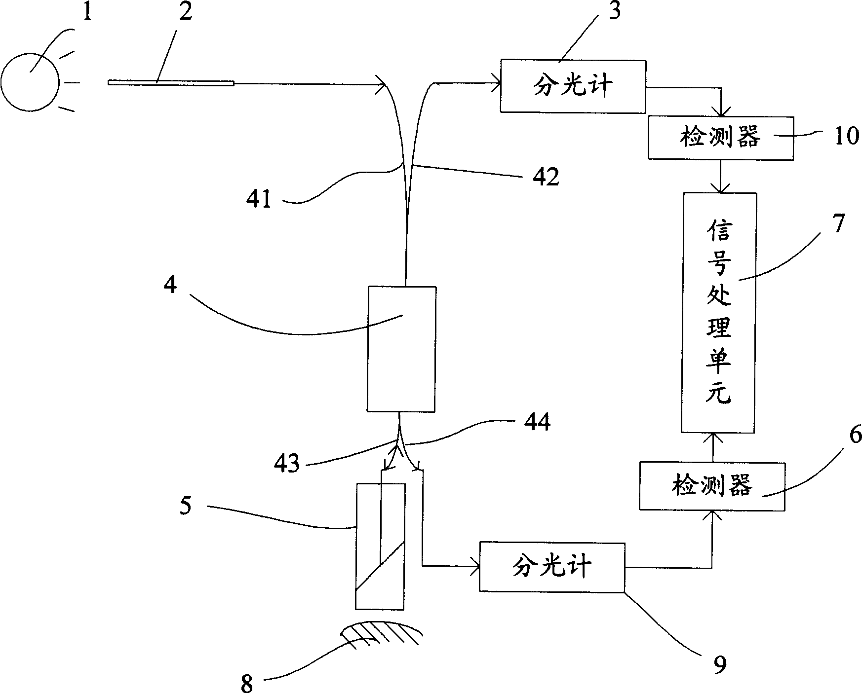
[0008] The reflectance measuring system of the present invention is suitable for measuring the surface reflectance of various optical components, and is especially suitable for measuring the surface reflectance of an optical component whose surface to be measured is a curved surface.

[0009] see figure 1 , the reflectivity measurement system includes a light source 1, a polarization maintaining fiber 2, a first spectrometer 3 (spectrometer), a polarization maintaining fiber direction coupler 4, a collimator lens 5, a first detector 6 (detector ), a signal processing unit 7, a second spectrometer 9 and a second detector 10, the reflectance measurement system is used to measure the reflectance of the surface of the object to be measured 8.

[0010] The light source 1 is a white light source, such as a halogen lamp, and 99.9% of its light is non-polarized light. The light source 1 is driven by AC (Alternating Current) modulation, so that the light emitted by the light source 1 i...


PUM


Abstract

A measurement system of reflectivity is prepared as setting light source to be nonpolarization light source; forming polarization holding fibre direction coupler by a light incoming end , a light outgoing end, a measuring end and a reference light output end; connecting light incoming end to polarization holding fibre; connecting bispectrometer one end separately to light outgoing end and reference light output end with another end being connected to bidetector; connecting detector one end to signal processing unit with another end being connected to bispectrometer; aligning said measuring end to surface of object to be measured.

Description

【Technical field】 [0001] The invention relates to a reflectivity measurement system, in particular to a reflectivity measurement system in which the surface of an object to be measured is a curved surface. 【Background technique】 [0002] An existing reflectance measurement system, as disclosed in U.S. Patent No. 4,831,276 published on May 16, 1989, the light emitted by the light source is focused into a beam of parallel light through a series of lenses and a contracted aperture, and then reflected by a mirror and After being focused to a point by the lens, it reaches the surface to be measured, is reflected by the surface to be measured, passes through some optical components, and then reaches the signal processing unit, thereby obtaining the reflectivity of the surface to be measured. The disadvantage of this measurement system is that it includes many optical components, and the structure is more complex; the optical path assembly of separate components is used to collect ...

Claims


Application Information

Patent Timeline
Patent Type & Authority Applications(China)
IPC IPC(8): G01N21/55
Inventor 林志泉
Owner HONG FU JIN PRECISION IND (SHENZHEN) CO LTD
Why Eureka
Try Eureka