
Method and device for deriving geodetic distance data

A technology of distance information and geodetic surveying, which is applied in the directions of measuring devices, measuring distances, measuring instruments, etc., can solve the problems of insufficient measurement accuracy, accurate measurement, and lack of multi-target capability, so as to reduce the influence of interference and achieve high-precision system analysis. Effect

Active Publication Date: 2006-03-22
LEICA GEOSYSTEMS AG
View PDF3 Cites 4 Cited by
  • Summary
  • Abstract
  • Description
  • Claims
  • Application Information

AI Technical Summary

Problems solved by technology

Therefore, distances to contours such as edges on objects cannot be accurately measured using semiconductor laser-based range finders
[0011] As a result, the main disadvantage of all previously known measuring principles is that either the operating range for reflectorless target objects is insufficient or the measuring accuracy is insufficient
[0012] Another disadvantage is the technically unrealized multi-target capability

Method used


Image

  • Method and device for deriving geodetic distance data
  • Method and device for deriving geodetic distance data
  • Method and device for deriving geodetic distance data

Examples


Embodiment Construction

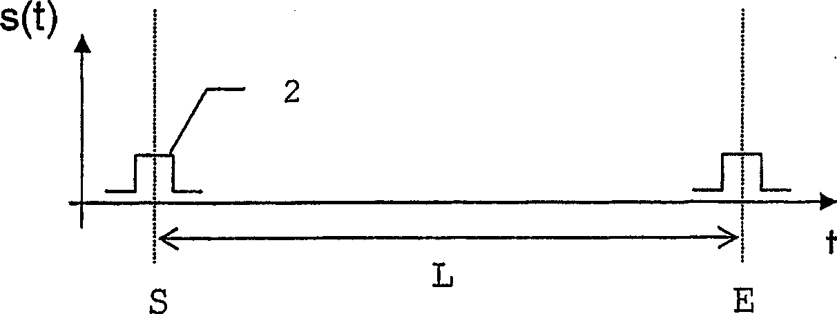
[0142] Figure 1a - b shows a schematic diagram of a pulse measurement method according to the prior art.

[0143] exist Figure 1a In this case, a light pulse 2 is emitted by a transmitter 1 and is again detected by a receiver 4 after being reflected by an object such as a retroreflector 3 . Usually, the transmitter 1 and the receiver 4 are configured in one instrument.

[0144] The distance is calculated from the transit time L which is the time difference between the emission start time S and the reception time E of the light pulse 2 . The reception time is here determined by characteristic evaluation of the signal pulse s(t), for example by exceeding a signal threshold value or by determining the center of gravity of the integrated pulse curve.

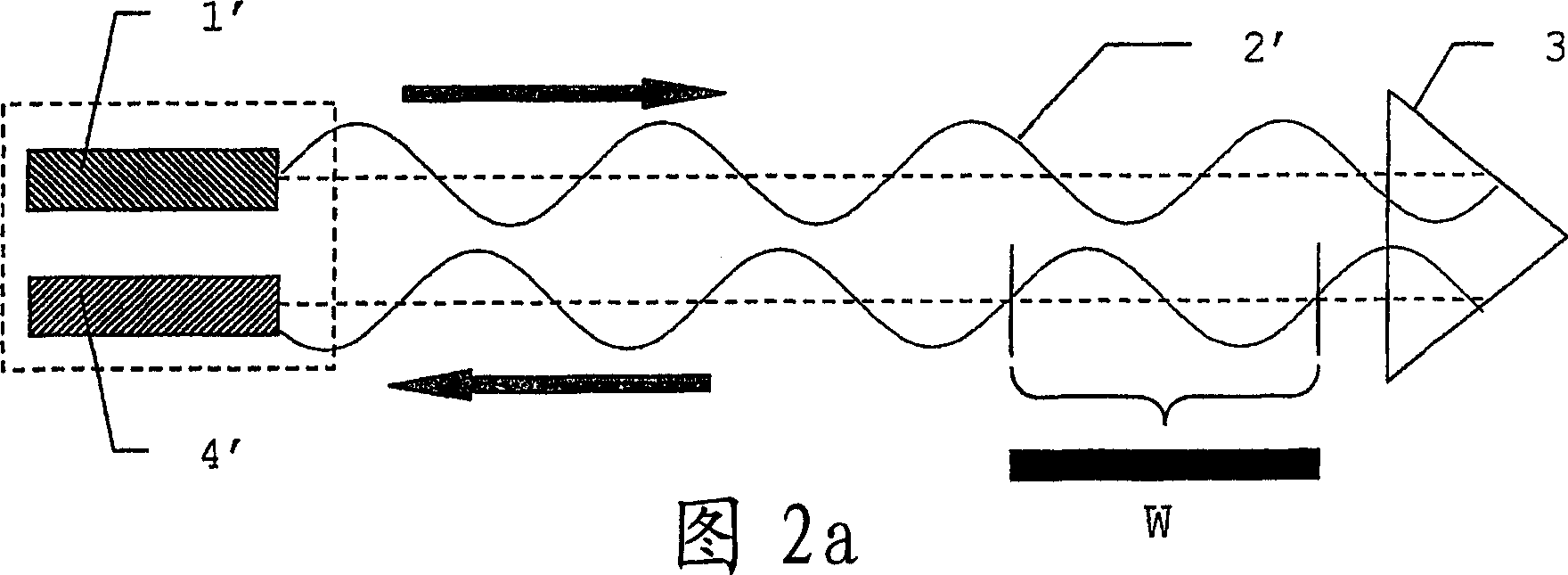
[0145] Figures 2a-b show a schematic diagram of a phase measurement method according to the prior art for determining the distance between an instrument and a target.

[0146] In Fig. 2a, a modulated optical signal is emitted ...


PUM


Abstract

A method for extracting geodetic / geodesic distance / ranging information with a signal generator for generating at least two HF modulation frequencies in the MHz- up to the GHz-range requires a system with a system-input, an optical radiation source , at least one target object (3a, 3b) and a receiver (4'') with a system output and an analysis / evaluating electronics. Initially, the system is excited with at least two , especially synthetic, modulation frequencies, preferably a group of discrete modulation frequencies, by applying at least one excitation signal at the system input. At least one system response is picked up at the system output and distance / ranging information is derived from the signal shape of the system response by the analysis electronics. Independent claims are included for (a) a device for carrying out the method, for (b) a geodetic / geodesic measurement instrument, especially a theodolite, for (c) a scanner for three-dimensional image-scanning and for (d) use of the device.

Description

technical field [0001] The invention relates to a method and a device for deriving geodetic distance information according to the preamble of claim 1 or 23, as well as a geodetic surveying instrument according to claim 29, a scanning device according to claim 31 Instrument and use of the device according to claims 32 to 34. Background technique [0002] Carrying out distance measurements is a technically standard task for which many solutions have been implemented using optical systems, among which tachymeters are typical measuring instruments for measuring tasks in geodesy and the construction industry. In recent years, tachymeters equipped with reflectorless measuring distance meters (EDM) have become more and more established. [0003] Initially, the working distance to be measured is 60m, but with the increasing popularization of the instrument, the requirements for its working distance are getting higher and higher. Today, the instrument measures up to 200m without a ...

Claims


Application Information

Patent Timeline
Patent Type & Authority Applications(China)
IPC IPC(8): G01C3/08G01S7/483G01S17/08G01C15/00G01S7/481G01S7/4865G01S7/487G01S13/22G01S17/26
CPCG01C3/08G01S17/102G01S7/4865G01S7/487G01S13/227G01S7/481G01S17/26
Inventor 于尔格·欣德林保罗·本茨马丁·德朗热
Owner LEICA GEOSYSTEMS AG
Learn More