Burner

A combustion device and burner technology, which is applied in the direction of combustion method, combustion control, combustion equipment, etc., can solve the problems of air volume reduction, reference current value reduction, and inability to accurately obtain air volume, so as to reduce adjustment work and high-precision air volume correction Effect

Active Publication Date: 2006-03-29
RINNAI CORP
View PDF2 Cites 14 Cited by
  • Summary
  • Abstract
  • Description
  • Claims
  • Application Information

AI Technical Summary

Problems solved by technology

However, according to this configuration, since the reference current value is determined to be a specific value during use, the following problems will arise. For example, due to year-by-year deterioration (dust accumula

Method used


Image

  • Burner
  • Burner
  • Burner

Examples


Embodiment Construction

[0019] One embodiment of the present invention will be described with reference to the drawings.

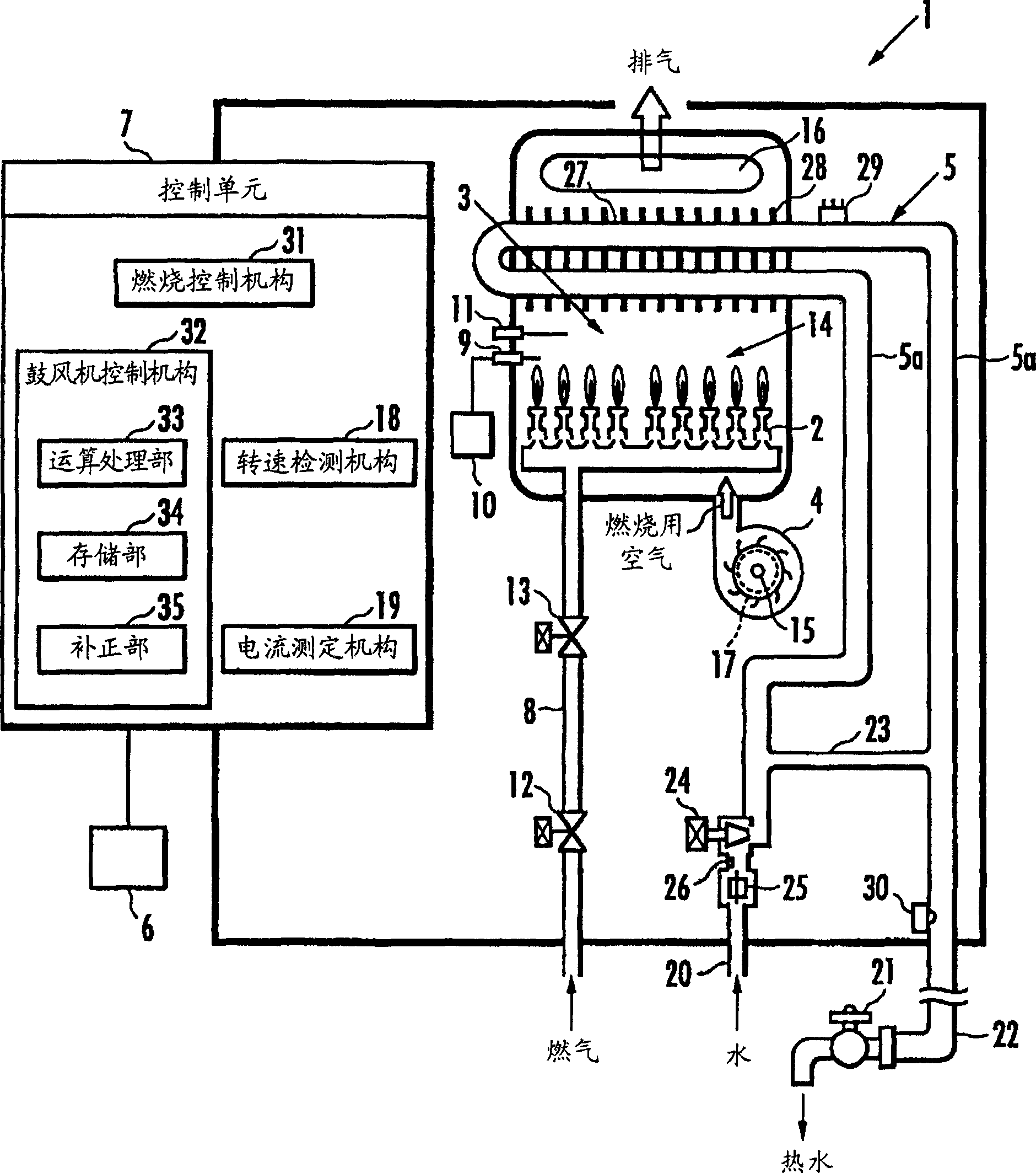
[0020] figure 1 The combustion device 1 shown is a water heater, which has: a burner 2, a ventilation system 3, which includes the burner 2; a blower 4, which is arranged on the ventilation system 3 and can forcefully Combustion air is supplied to the burner 2; the water passage 5; and the control unit 7 which controls the hot water supply operation based on the setting of the hot water supply temperature by the remote controller 6 or the like.

[0021] The burner 2 is ignited and burned by igniting the gas supplied through the gas passage 8 through the ignition electrode 9 and through the igniter 10 ; the state of its combustion flame is detected by the flame detection rod 11 . On the gas passage 8, a main solenoid valve 12 and a speed regulating solenoid proportional valve 13 are sequentially arranged from upstream to downstream. The speed-regulating proportional solenoid val...


PUM


Abstract

To provide combustion equipment. This combustion equipment is provided with a fan control means which controls a fan for supplying a burner with combustion air. The fan control means is equipped with a first operation means which computes the revised value of a fan current from the difference between a detected current value and a reference current value on the basis of fan revolution - fan current properties that are predetermined corresponding to the fan revolution - fan current properties that show the lower limit of the dispersion of the current of the fan, a second operation means which computes the fan current recognized value being the difference between the detected current value and the fan current revised value, a third operation means which computes a fan correction value based on the fan current recognized value, a memory means which stores the reference current value, the fan current revised value, the fan current recognized value, and the fan correction, and a correction means which corrects the quantity of air of the fan based on the fan correction value.

Description

technical field [0001] The present invention relates to a combustion device for controlling the current of the blower so that the rotation speed of the blower coincides with the target rotation speed corresponding to the combustion amount of the burner, wherein the blower is installed in the ventilation system including the above-mentioned burner, and Combustion air is supplied to the burner. Background technique [0002] In such a combustion device, the current of the blower motor is controlled so that the rotational speed of the blower that supplies combustion air to the burner matches the target rotational speed at which the burner can perform good combustion. However, when the ventilation system provided with the blower is blocked, even if the blower current is controlled so that the speed of the blower matches the target speed, the combustion air supplied to the burner is still insufficient, resulting in the combustion of the burner. poorly rendered. Thus, according t...

Claims


Application Information

Patent Timeline
IPC IPC(8): F23N3/08F04D27/00H02P5/00F23N5/24H02P29/00H02P29/68
CPCF23L5/02
Inventor 冈本英男太田弘逸
Owner RINNAI CORP
Why Eureka
Try Eureka