

Millimeter-wave double-pole double-throw switch circuit
A double-pole double-throw switch, millimeter wave technology, applied in the direction of circuit, logic circuit connection/interface layout, electrical components, etc., can solve problems such as high cost and poor consistency, to eliminate influence, avoid reliability problems, and eliminate phase effect of error
- Summary
- Abstract
- Description
- Claims
- Application Information
AI Technical Summary
Problems solved by technology
Method used
Image

Examples
Embodiment Construction
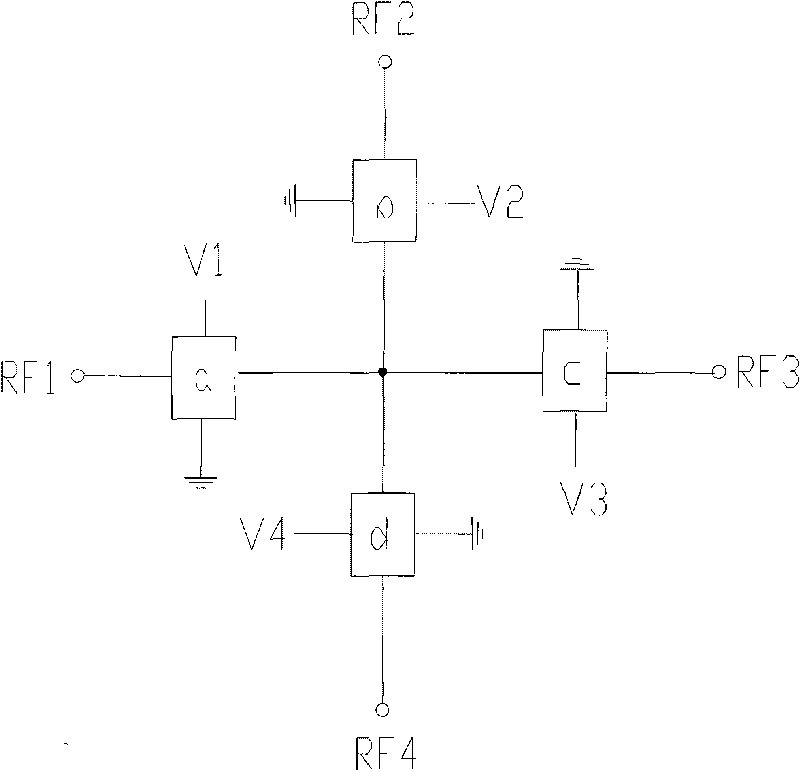
[0011] see figure 1 , the millimeter-wave double-pole double-throw switch circuit provided by the present invention is composed of four input and output ports RF1, RF2, RF3, RF4 and four input and output ports RF1, RF2, RF3, RF4 supporting gating control circuit a , composed of b, c, and d, the branch circuits connected to the four input and output ports are connected in a cross shape, and the two ends of the same straight line are port RF1 and port RF3, and the two ends of the other straight line are respectively port RF2 and port RF4 forms a symmetrical branch structure with intersection 0 as the center, and the ports of the above branches are connected to intersection 0 through gating control circuits a, b, c, and d.
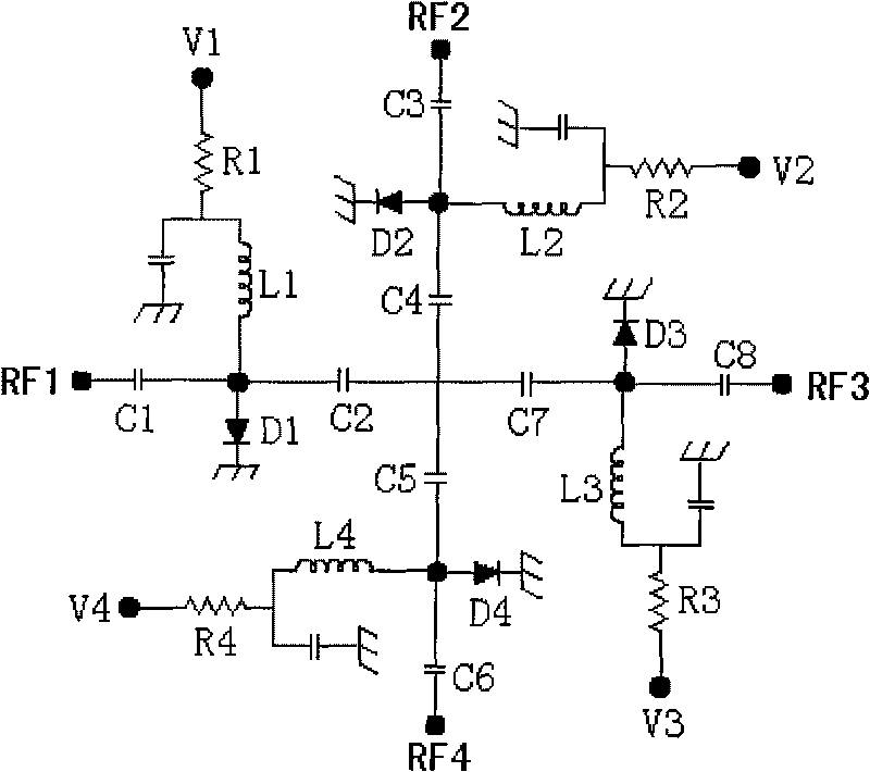
[0012] see figure 2 , the structure of the gating control circuit is that the voltage input V1 is connected in series with the voltage dividing resistor R1, and its lower end is divided into two parallel connections, one path is grounded through a DC blocki...
PUM
 Abstract
Description
Claims
Application Information