

Manufacturing method of heat radiation device
A technology of heat dissipation device and manufacturing method, which is applied in the directions of manufacturing tools, cooling/ventilation/heating modification, semiconductor/solid-state device manufacturing, etc. lowering rate
- Summary
- Abstract
- Description
- Claims
- Application Information
AI Technical Summary
Problems solved by technology
Method used
Image

Examples
Embodiment Construction
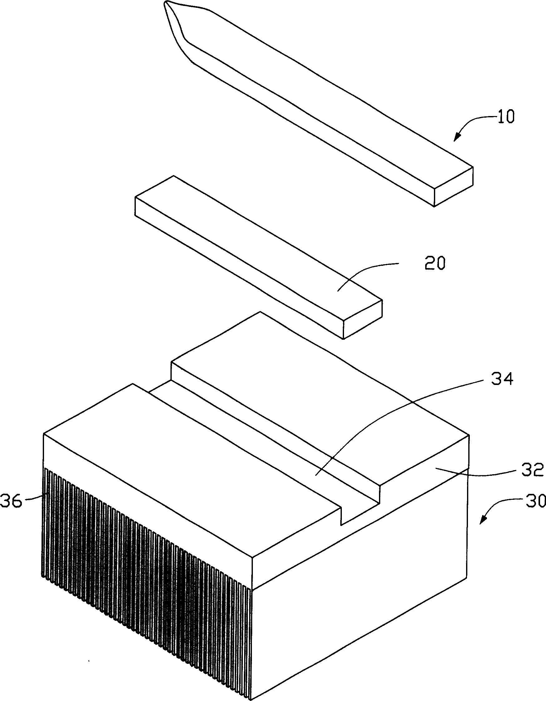
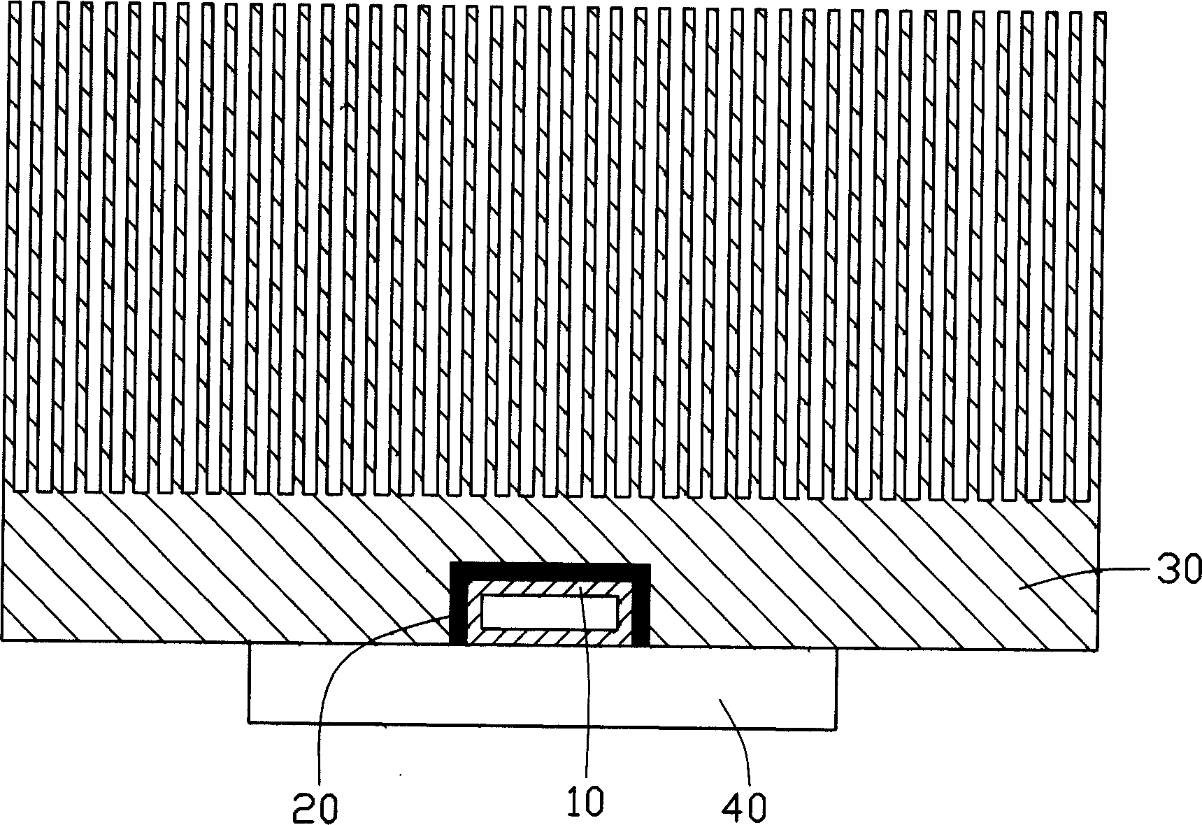
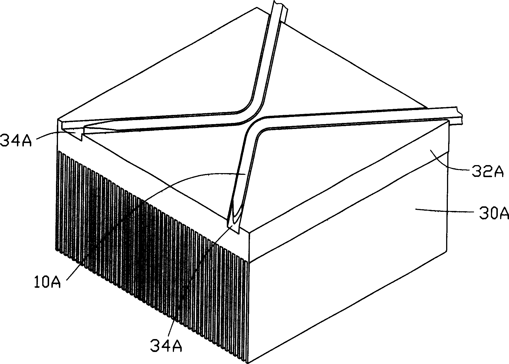
[0012] Please refer to figure 1 and figure 2 , the heat dissipation device of the present invention includes a heat sink 30 and a heat pipe 10, and its manufacturing method comprises the following steps: 1) providing a heat pipe 10; 2) providing a heat sink 30, which includes a base 32, on one side of the base 32 A groove 34 is provided for accommodating the heat pipe 10; a plurality of cooling fins 36 are provided on the other side of the base 32; 3) an electrode 20 such as a tin bar is provided, and the electrode 20 and the heat pipe 10 are placed in the groove in turn. In the groove 34, the welding rod 20 is clamped between the heat pipe 10 and the radiator 30; 4) heating to melt the welding rod 20, and press a plane such as a metal plate to the side where the groove 34 is provided on the base 32, Thus, the heat pipe 10 is fixed in the groove 34 .
[0013] Due to the poor fluidity of the welding rod 20, the gap between the heat pipe 10 and the radiator 30 can be filled a...
PUM
 Abstract
Description
Claims
Application Information