
Plasma display device

A technology of plasma display and partition wall, applied in alternating current plasma display panels, tube structural parts, sustain/scan electrodes, etc., can solve the problems of gray scale and efficiency reduction, long distance, increase discharge start voltage, discharge sustain voltage, etc.

Inactive Publication Date: 2006-04-05
NANJING LG TONGCHUANG COLOR DISPLAYS SYST CO LTD
View PDF0 Cites 0 Cited by
  • Summary
  • Abstract
  • Description
  • Claims
  • Application Information

AI Technical Summary

Problems solved by technology

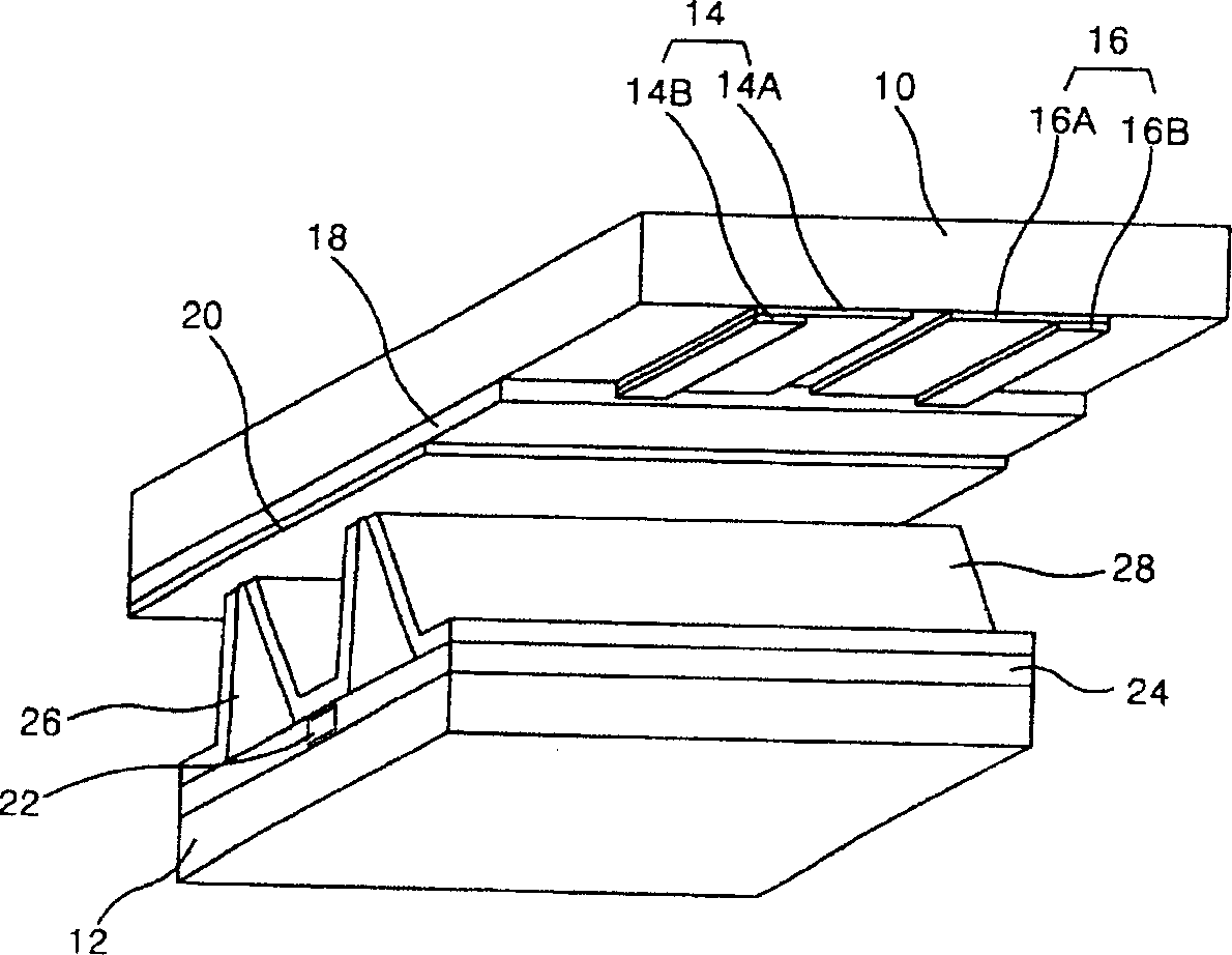
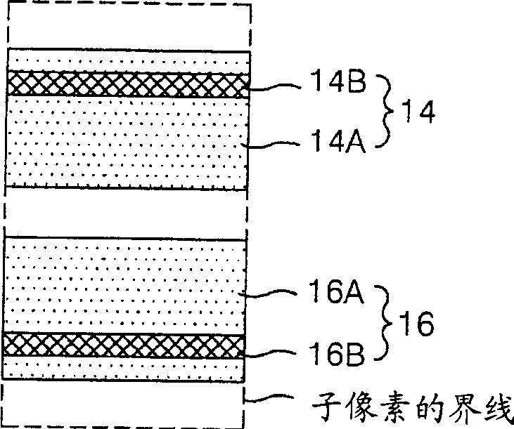
[0015] In addition, in the existing PDP, metal electrodes 14B, 16B are formed on the outer edges of the transparent electrodes 14A, 16A, and the distance between the metal electrodes 14B, 16B is relatively long, so the discharge start voltage and discharge sustain voltage will be increased.
Because of this, the power consumption in the existing PDP will increase, and its gradation and efficiency will also decrease.

Method used


Image

  • Plasma display device
  • Plasma display device
  • Plasma display device

Examples


Embodiment Construction

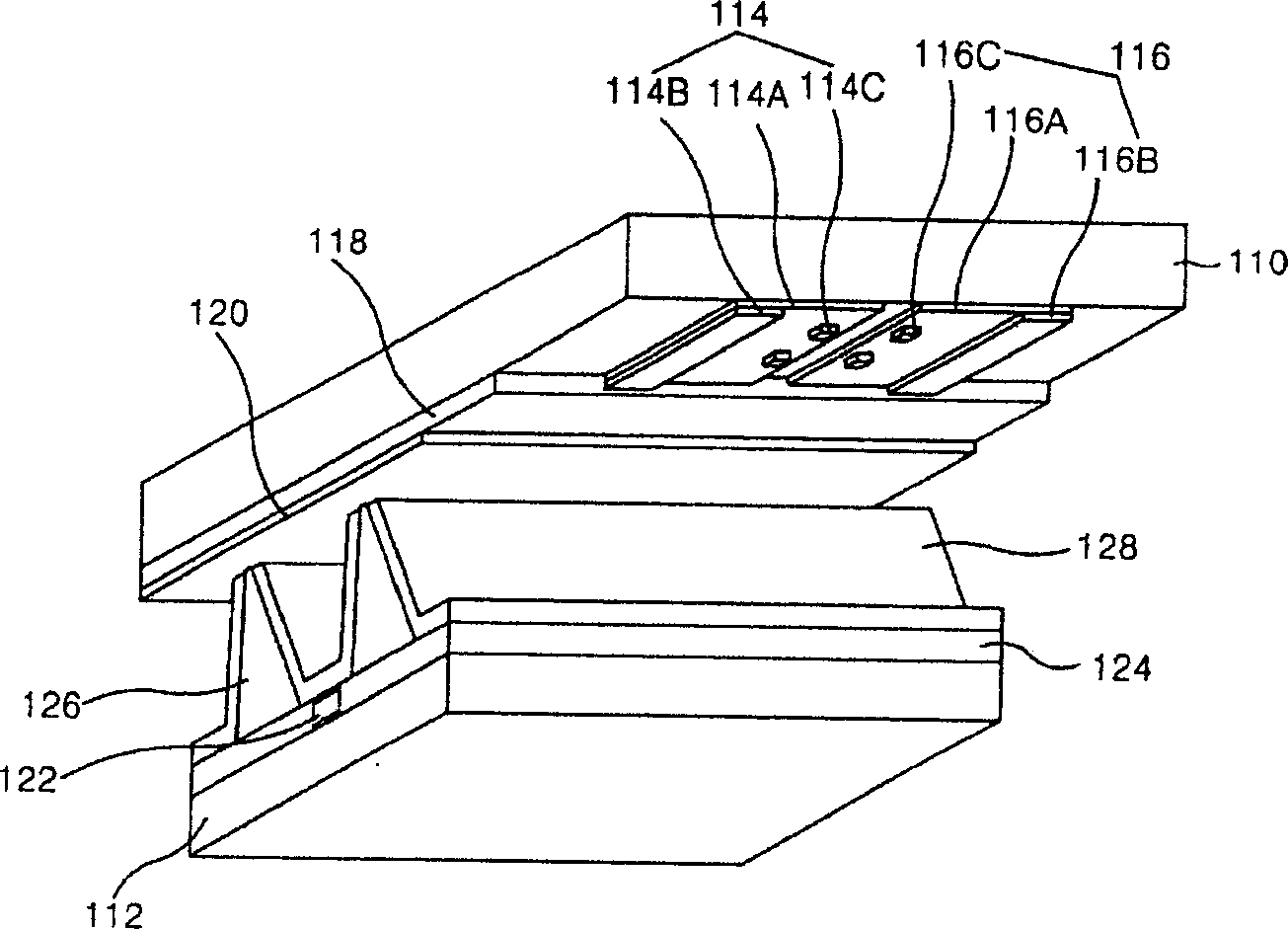
[0049] Below, refer to Figure 3 to Figure 12 , the embodiment of the plasma display of the present invention will be described in detail.

[0050] refer to image 3 The plasma display (Plasma Display Panel: hereinafter referred to as "PDP") in the first embodiment of the present invention is composed of the following components: a pair of sustain electrodes 114, 116 formed sequentially on the upper substrate 110; The upper plate of the layer 118 and the protective film 120 ; the address electrodes 122 formed on the lower substrate 112 in sequence; the lower dielectric layer 124 ; the lower plate with the isolation wall 126 and the phosphor layer 128 . The upper substrate 110 and the lower substrate 112 are separated in parallel by a partition wall 126 .

[0051] Charges are accumulated in the upper dielectric layer 118 and the lower dielectric layer 124 . The protective film 120 can prevent the upper dielectric layer 118 from being damaged by sputtering, thereby prolonging...


PUM


Abstract

Disclosed a plasma display comprises a couple of maintaining electrodes formed on the upper base plate; a upper plate with upper dielectric medium layer and the protective film; a address electrode formed on the lower base plate; a lower dielectric medium layer; a lower plate with dividing wall and fluorophor layer. Wherein, the upper base plate and the lower base plate are parallel separated via the dividing wall, and said couple of maintaining electrodes comprises transparent electrodes each of which is separated and metal electrodes formed on the edges of the side of said transparent electrodes, and several auxiliary metal electrode groups formed on the opposite side of said transparent electrodes. The invention can induce stronger discharge via increasing the electric field of the center of discharge unit of discharge space, to improve the grey scale and the efficiency.

Description

(1) Technical field [0001] The invention relates to a plasma display, in particular to a plasma display capable of improving grayscale and efficiency. (2) Background technology [0002] Recently, various flat panel display devices capable of reducing the weight and volume of a cathode ray tube (Cathode Ray Tube) have been developed. Such flat panel display devices include liquid crystal display (Liquid Crystal Display: LCD), field emission display (Field Emission Display: FED), plasma display (Plasma Display Panel: hereinafter referred to as "PDP"), and electroluminescence (Electro Luminescence). : EL) display device, etc. [0003] Among them, PDP is a display element utilizing the principle of gas discharge, and has the advantage of being easy to manufacture a large display screen. The most representative is figure 1 Shown is a three-electrode AC creeping discharge type PDP that has three electrodes and is driven by an AC voltage. [0004] figure 1 It is an oblique vie...

Claims


Application Information

Patent Timeline
Patent Type & Authority Applications(China)
IPC IPC(8): H01J17/04H01J17/49H01J11/10H01J11/24
Inventor 闵雄基姜晸远
Owner NANJING LG TONGCHUANG COLOR DISPLAYS SYST CO LTD
Learn More