

Packet reception control device and method
A technology for receiving control and data packets, applied in data exchange networks, digital transmission systems, electrical components, etc., and can solve problems such as difficulty in fixing emergency processing time periods.
- Summary
- Abstract
- Description
- Claims
- Application Information
AI Technical Summary
Problems solved by technology
Method used
Image

Examples
Embodiment 1
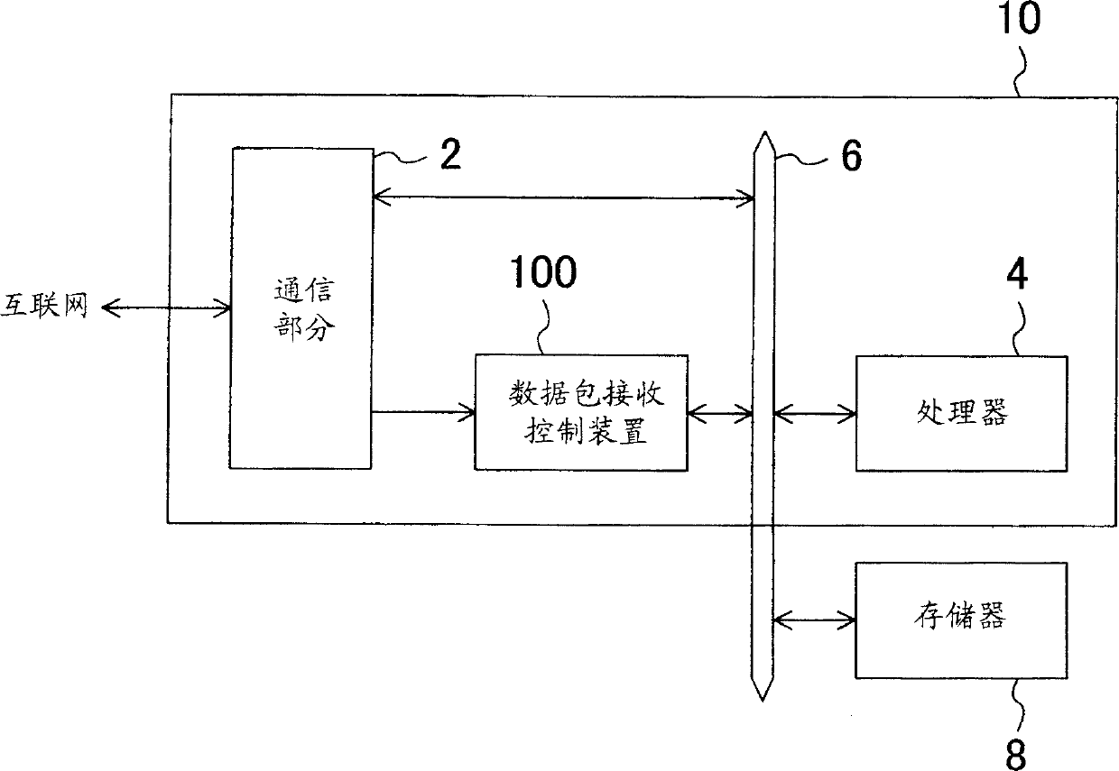
[0145] Fig. 1 is a block diagram of a packet communication system according to Embodiment 1 of the present invention. The packet communication system of FIG. 1 includes a memory 8 and a semiconductor integrated circuit 10 . The semiconductor integrated circuit 10 includes a communication section 2 , a processor 4 and a packet reception control device 100 . For example, processor 4 may be a CPU or a digital signal processor (DSP).
[0146] The communication section 2 transmits a packet to or receives a packet from the network, and outputs the received packet (reception packet) to the reception control device 100 . In addition, the communication section 2 also transmits or receives packets of data to or from the processor 4 and the memory 8 via the bus 6 as needed.
[0147] The packet reception control device 100 outputs the packet received from the communication section 2 to the memory 8 through the bus 6 . Processor 4 reads the data packets from memory 8 . The packet recep...
Embodiment 2
[0175] Fig. 6 is a block diagram of a data packet reception control device according to Embodiment 2 of the present invention. The packet reception control device 200 of FIG. 6 includes a load detection section 220 and a reception notification section 270 as a reception control section. The data packet reception control device 200 is used to replace the data packet reception control device 100 in the data packet communication system of FIG. 1 .
[0176] The load detection section 220 includes a timer counter 222 , a monitoring section 224 and a load calculation section 228 . The reception notification section 270 includes: an upper limit value register 272 , a reception notification stop control section 274 , and a counter 276 .
[0177] The processor 4 executes the task of the access monitoring section 224 . This task is periodically started by the processor 4 on the multitasking OS. The period of the task is set to a time shorter than a timeout (timeout) of the timer coun...
Embodiment 3
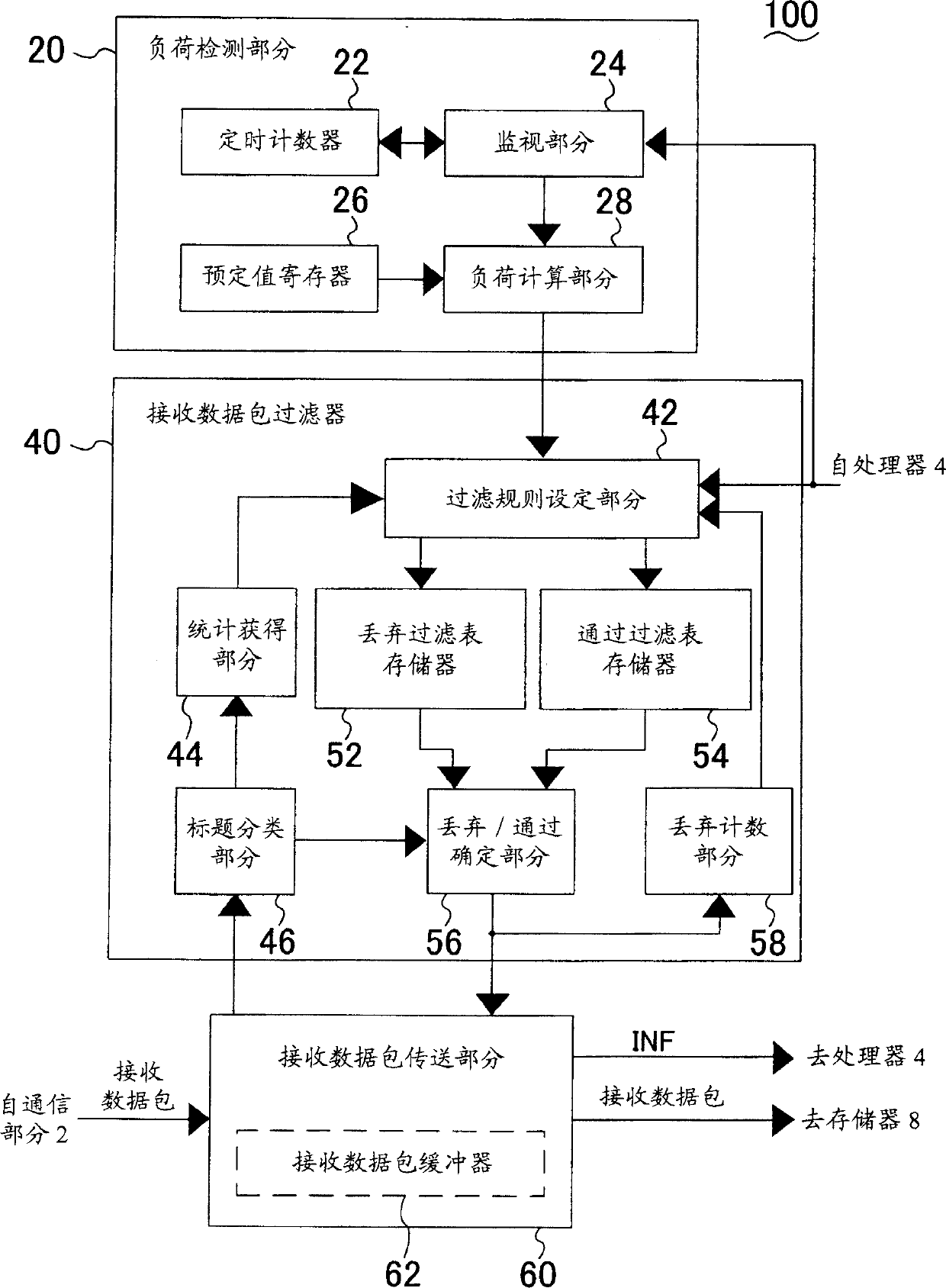
[0195] Fig. 7 is a block diagram of a data packet reception control device according to Embodiment 3 of the present invention. The packet reception control device 300 of FIG. 7 includes a load detection section 320 , an overload countermeasure section 330 , a reception packet filter 340 as a reception control section, and a reception packet transmission section 360 . The data packet reception control device 300 is used to replace the data packet reception control device 100 in the data packet communication system of FIG. 1 .
[0196] The load detection section 320 includes a timer counter 322 and a monitoring section 324 . The overload countermeasure section 330 includes an overload control section 332 , a counter 334 and a discard count section 336 . The reception packet filter 340 includes a filter rule setting section 342 , a statistics obtaining section 344 , a header classification section 346 , a drop filter table memory 352 , a pass filter table memory 354 , and a drop...
PUM
 Abstract
Description
Claims
Application Information