
High efficiency machine for cutting metallic wire

A metal wire and wire breaking machine technology, which is applied in the field of high-efficiency wire breaking machines for metal wires, can solve the problems of inability to press down to cut multiple metal wires at the same time, low efficiency, slow cutting speed, etc., to save manpower, high efficiency, Cut off the effect of fast speed

Inactive Publication Date: 2006-04-12
刘堃
View PDF0 Cites 2 Cited by
  • Summary
  • Abstract
  • Description
  • Claims
  • Application Information

AI Technical Summary

Problems solved by technology

The bolt cutter can only cut one metal wire at a time, and cannot cut off multiple metal wires at the same time. The cutting speed is slow and the efficiency is low.

Method used


Image

  • High efficiency machine for cutting metallic wire
  • High efficiency machine for cutting metallic wire
  • High efficiency machine for cutting metallic wire

Examples


Embodiment 1

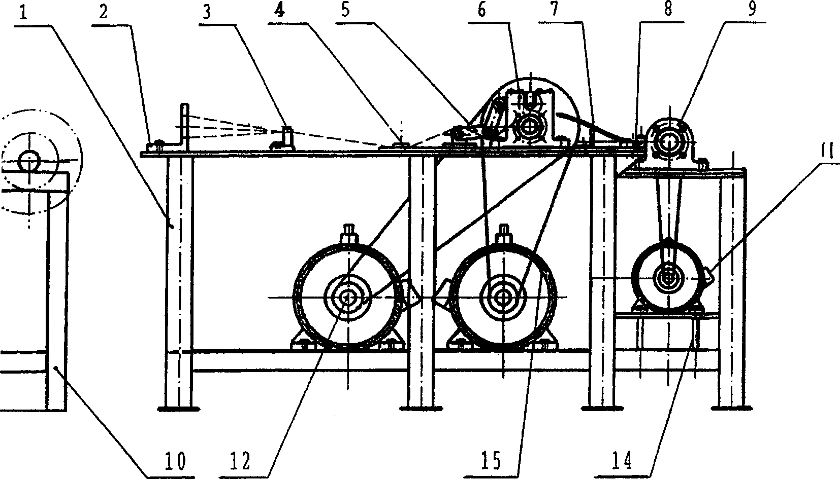
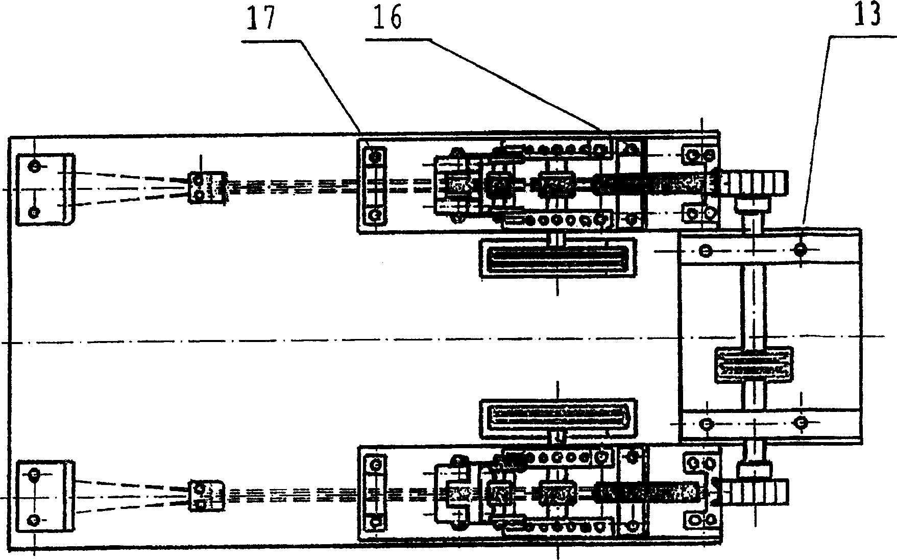
[0020] Embodiment 1: This wire breaking machine has a frame 1, and the frame 1 is connected with a wire trimmer and a wire feeding device, and one end of the frame 1 is connected with a wire breaker 9, and the other end is connected with a material tray device 10. The bottom of the frame 1 is connected with motors 14, 15 and 12, wherein the motors 15 and 12 are speed-regulating motors.

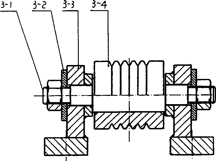
[0021] The wire trimming device is composed of a wire drawing die 2, a front wire trimming die 3 and a rear wire trimming die 4. The wire drawing die 2, the front wire trimming die 3 and the rear wire trimming die 4 are arranged and installed on the frame 1 in sequence; the wire drawing die 2 has a " L" shaped bracket with wire drawing holes on the bracket; the front wire trimming die 3 has an "L" shaped bracket with wire trimming holes on the bracket; the rear wire trimming die 4 is composed of upper die and lower die Both are two flat plates stacked together, and there are holes on the end f...


PUM


Abstract

An efficient wire cutting machine for metallic wire is composed of a machine frame, a wire straightening device, a wire feeder, a wire cutter with the blade rotating at high speed, a wire reel, and a motor. Its advantages are high speed, simple structure and high automation level.

Description

technical field [0001] The invention relates to a wire cutting machine, in particular to a high-efficiency wire cutting machine for metal wires. Background technique [0002] At present, people generally use bolt cutters when cutting off the thinner metal wire rod of diameter, and bolt cutters have a support shaft, and at support shaft two sides, a side has a jaw, and the other side has a handle. When in use, it is operated manually, and the metal wire is put into the jaw of the bolt cutter, and the handle on the other side is pressed by hand, and the supporting shaft is used as a fulcrum, and the metal wire is cut off by using the principle of leverage. The bolt cutter can only cut off one metal wire rod by pressing down once, but cannot cut off multiple metal wire rods simultaneously by pressing down once, and the cutting speed is slow and the efficiency is low. Contents of the invention [0003] The object of the pres...

Claims


Application Information

Patent Timeline
Patent Type & Authority Applications(China)
IPC IPC(8): B21F11/00B21F1/02B21F23/00B21F9/00
Inventor 刘堃刘春疆
Owner 刘堃
Learn More