
Device for altering the valve timing in an internal combustion engine

A technology for controlling time and ventilation valves, applied in valve devices, engine control, mechanical equipment, etc.

Active Publication Date: 2006-04-12
SCHAEFFLER TECH AG & CO KG
View PDF2 Cites 6 Cited by
  • Summary
  • Abstract
  • Description
  • Claims
  • Application Information

AI Technical Summary

Problems solved by technology

[0016] A major disadvantage of control valves connected to camshaft adjusters with locking in the center position is that the pressurized oil connection is connected to one of the two working connections without bypass flow

Method used


Image

  • Device for altering the valve timing in an internal combustion engine
  • Device for altering the valve timing in an internal combustion engine
  • Device for altering the valve timing in an internal combustion engine

Examples


Embodiment Construction

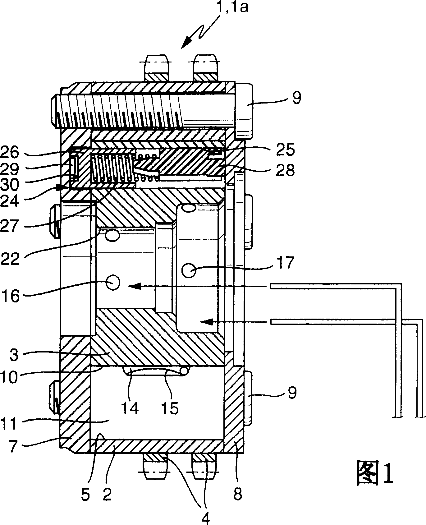
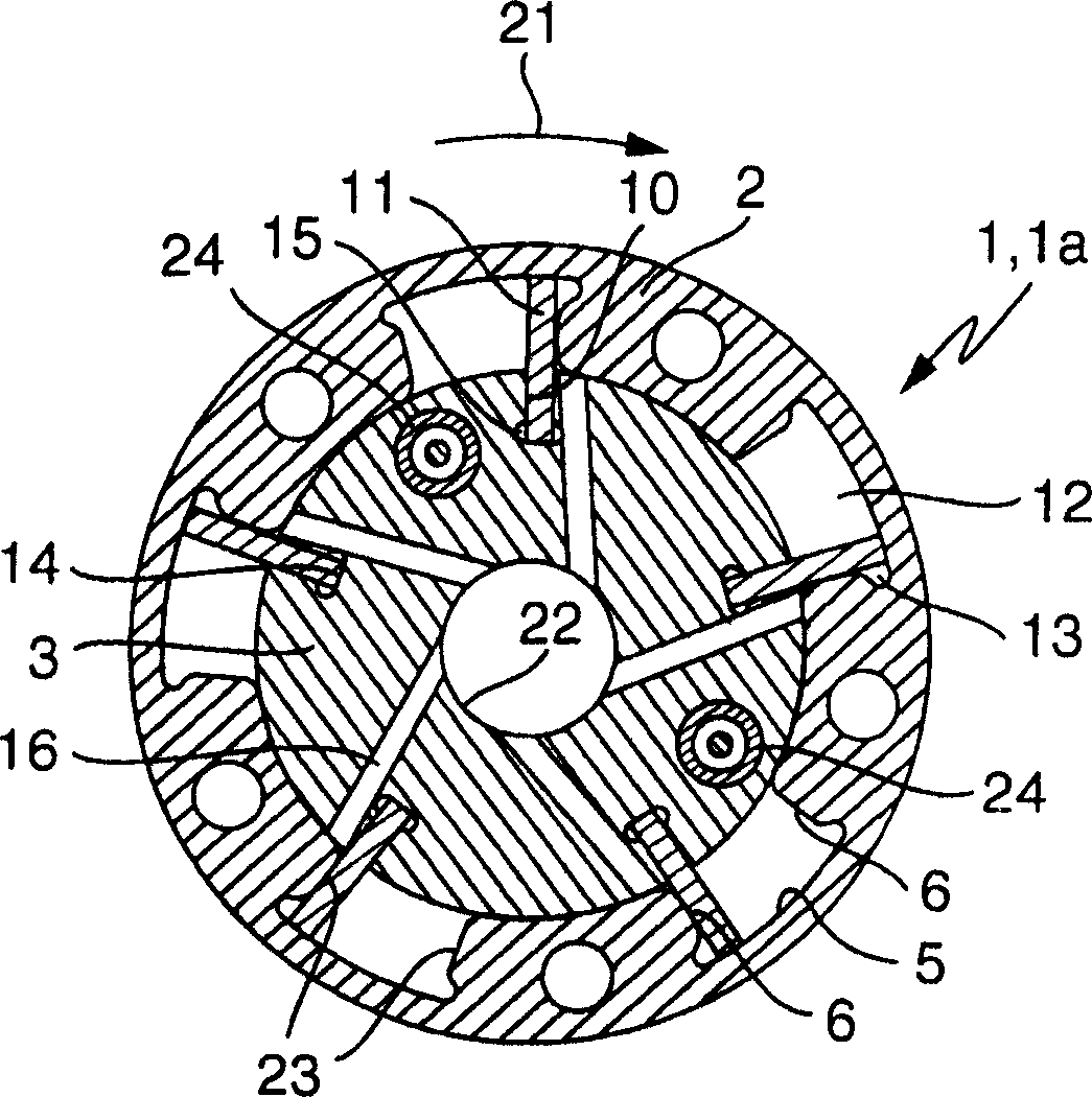
[0047] 1 and 2 show a hydraulic adjustment device 1 a of a device 1 for varying the actuation times of gas exchange valves of an internal combustion engine. The adjusting device 1 a essentially consists of a stator 2 and a rotor 3 arranged concentrically therewith. The drive wheel 4 is connected to the stator 2 in a rotationally fixed manner and is designed as a sprocket in the illustrated embodiment. Likewise the embodiment of the drive wheel 4 can be a pulley or a gear. The stator 2 is rotatably mounted on the rotor 3 , wherein in the illustrated embodiment the inner peripheral surface of the stator 2 is provided with five gaps 5 spaced from one another in the circumferential direction. The gap 5 is limited in the radial direction by the stator 2 and the rotor 3 , in the circumferential direction by the two side walls 6 of the stator 2 and in the axial direction by the first side cover 7 and the second side cover 8 . Each gap 5 is hermetically closed in this way. The firs...


PUM


Abstract

The invention relates to a device (101) for varying the control time of a gas exchange valve of an internal combustion engine, which has a hydraulic adjustment device (102) and a control valve (103). The device (101) according to the invention is provided with an intermediate position locking of the hydraulic adjustment device (102). Furthermore, the device (101) according to the invention ensures that, when the adjustment unit (112) is interrupted, the control valve (103) is adjusted, the hydraulic adjustment device (102) is locked in the middle position and the locking remains until the adjustment unit (112) repair. Furthermore, the device (101) according to the invention can start the internal combustion engine in the locked position in the middle position without the movable element (105) of the hydraulic adjustment device (102) hitting the pressure chamber (104) when the internal combustion engine is started.

Description

technical field [0001] The invention relates to a device for varying the control timing of a gas exchange valve of an internal combustion engine according to the preambles of claims 1 , 2 and 3 . Background technique [0002] Camshafts are used in internal combustion engines to control the gas exchange valves. The camshaft is installed in the internal combustion engine in such a way that the cams mounted on the camshaft are located next to cam attachments, such as barrel tappets, rocker arms or swing arms. If the camshaft turns, the cam on the cam attachment is selected, which re-controls the gas exchange valve. The position and shape of the cam thus determine the degree of opening, the opening amplitude and even the opening and closing times of the gas exchange valve. [0003] Current motor concepts consist in a variable design of the valve actuator. On the one hand, the valve lift and valve opening should be variably adjusted until the individual cylinders are completel...

Claims


Application Information

Patent Timeline
Patent Type & Authority Applications(China)
IPC IPC(8): F01L1/344F01L1/46
CPCF01L2800/03F01L2001/34463F01L1/3442F01L2001/3443F01L2800/01F01L2001/34466F01L2001/34469F01L2103/00F01L2001/34426F01L2800/00F01L2303/00F01L1/34F01L1/344F02D13/02
Inventor 马可·施米特
Owner SCHAEFFLER TECH AG & CO KG
Learn More