Comparator with output offset correction and mos logical circuit

An oxide semiconductor and offset correction technology, applied in the field of comparators, can solve the problems of inconsistent output common mode level of MCML circuits, abnormal operation of MCML circuits, and limiting the maximum operating frequency and analytical capabilities of MCML circuits.

Active Publication Date: 2006-04-12
VIA TECH INC
View PDF0 Cites 9 Cited by
  • Summary
  • Abstract
  • Description
  • Claims
  • Application Information

AI Technical Summary

Problems solved by technology

When the minimum differential output voltage is too small, it will cause abnormal operation of the MCML circuit
Therefore, due to process variations, such as variations in the threshold voltage (Vt) of the differential pair transistors, the maximum operating frequency and resolution capability of the MCML circuit will be limited, and the output common-mode level of the MCML circuit will also be inconsistent.

Method used


Image

  • Comparator with output offset correction and mos logical circuit
  • Comparator with output offset correction and mos logical circuit
  • Comparator with output offset correction and mos logical circuit

Examples


Embodiment Construction

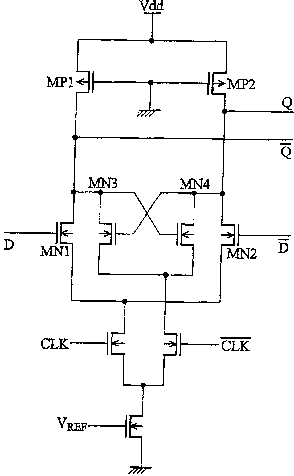
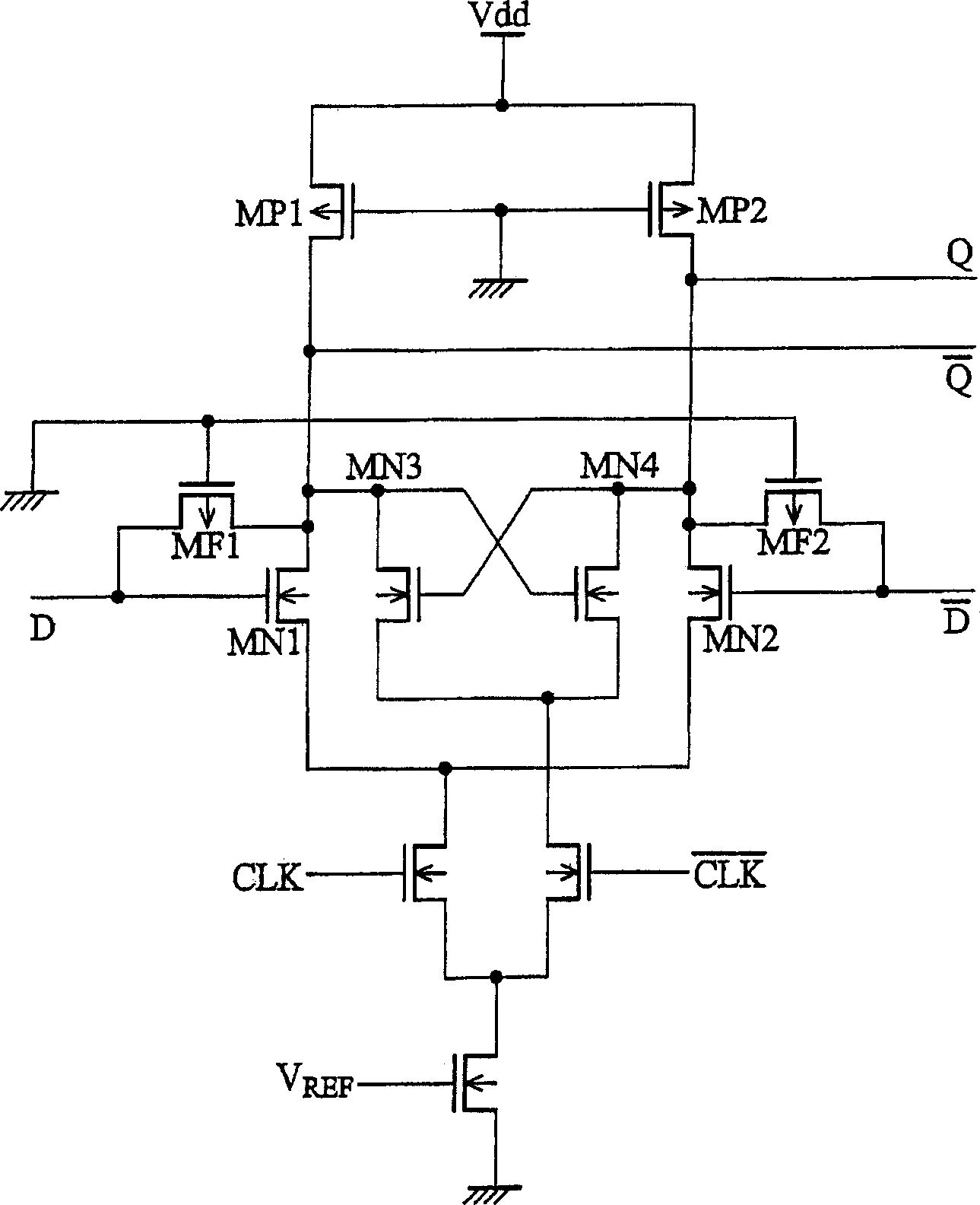
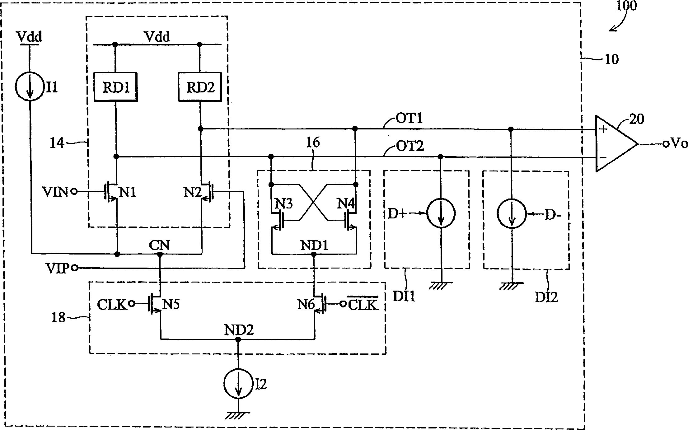
[0048] figure 2 is shown as an embodiment of the comparator of the present invention, while image 3 Shown is a schematic circuit diagram of a MOS current mode logic (MCML) circuit of the present invention. Such as figure 2 and image 3 As shown, the comparator 100 includes a metal oxide semiconductor current mode logic circuit (hereinafter referred to as MCML circuit) 10 and an output stage 20 .

[0049] The MCML circuit 10 receives input signals VIN and VIP, and generates differential logic signals on output terminals OT1 and OT2. MCML circuit 10 includes a coupling circuit 12 (shown only in image 3 middle), a differential input stage 14, a latch unit 16, a differential pair 18, a current source I2 (only shown in figure 2 middle), a correction unit (DI1 and DI2), and a booster I1 (only shown in image 3 middle). The boosting device I1 is used for pulling up the voltage level of the common node CN to the power supply voltage Vdd in a comparison mode.

[0050] The ...


PUM


Abstract

Provided are comparators outputting offset calibration. A MOS current mode logic (MCML) circuit receives input signals and generates differential logic signals on output terminals thereof, and comprises a calibration unit coupled to the output terminals, calibrating output offsets at the output terminals according to digital calibration codes. An output stage is coupled to the differential logic signals at the output terminals of the MCML circuit to amplify the differential logic signal and generate a comparison resulting signal.

Description

technical field [0001] The invention relates to a comparator, in particular to a comparator with output offset correction. Background technique [0002] Among various analog / digital converters (analog / digital converters; ADCs), such as fast analog / digital converters (flash ADC), interpolation analog / digital converters (interpolationADC), pipeline analog / digital converters ( pipeline ADC) and two-step analog / digital converter (two-step ADC), as well as high-speed receivers, such as PCI_Express receivers and DVI receivers, require high-speed comparators to meet the high-speed operation of digital circuits requirements. [0003] Differential logic circuits, such as MOS current mode logic (MCML) circuits, are very suitable for systems requiring high speed due to their high switching speed and low power consumption. Figure 1A and Figure 1B It is a circuit diagram of a traditional MCML circuit. As shown in the figure, if the threshold voltages (Vt) of transistors MN1 and MN2 ...

Claims


Application Information

Patent Timeline
IPC IPC(8): H03K19/0944H03K5/24H03M1/10
CPCH03K5/2481H03K5/249
Inventor 刘中鼎李耿民杨沛锋毕卓潘锐
Owner VIA TECH INC
Why Eureka
Try Eureka