Supercharge Your Innovation With Domain-Expert AI Agents!

Video optical receiver

An optical receiver and optical receiver technology, applied in electromagnetic receivers, optical fiber transmission, electromagnetic transceivers, etc., can solve the problems that optical receivers cannot use broadband, narrow bandwidth, and increase impedance transformation ratio.

Inactive Publication Date: 2006-04-12
SAMSUNG ELECTRONICS CO LTD
View PDF2 Cites 6 Cited by
  • Summary
  • Abstract
  • Description
  • Claims
  • Application Information

AI Technical Summary

Problems solved by technology

[0008] However, the impedance converter converts the high impedance value of the electrical signal converted by the photodiode into the 75Ω impedance value of the broadband optical amplifier, so that the impedance conversion ratio increases
However, the optical receiver cannot be used for a wide frequency band exceeding 2 GHz because the available bandwidth is narrowed

Method used


Image

  • Video optical receiver
  • Video optical receiver
  • Video optical receiver

Examples


Embodiment Construction

[0019] Hereinafter, embodiments according to the present invention will be described with reference to the drawings. For clarity and conciseness, detailed descriptions of well-known functions and configurations incorporated herein will be omitted since it may obscure the subject matter of the present invention.

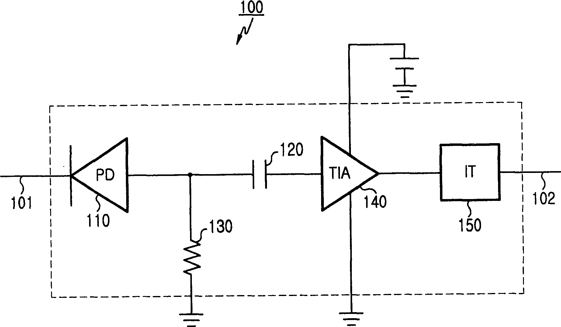
[0020] figure 1 Shown is a structural block diagram of the video overlay optical receiver 100 according to the first embodiment of the present invention. The video overlay optical receiver 100 includes: an optical receiver 110 for converting an optical signal into an electrical signal; a transimpedance amplifier (TIA) 140 having an output impedance value of 50Ω for amplifying the electrical signal; and an impedance transformer (IT) 150, configured to perform impedance transformation on the electrical signal amplified by the transimpedance amplifier 140, so as to obtain an output impedance of 75Ω. The receiver 100 also includes a resistor 130 for grounding direct cu...


PUM


Abstract

A video overlay optical receiver is disclosed. The receiver includes a light-receiving device arranged to convert an optical signal into an electrical signal and a transimpedance amplifier having an output impedance value of 50Omega for amplifying the electrical signal.

Description

technical field [0001] The present invention relates to an optical receiver, and more particularly to a video overlay optical receiver for receiving image signals. Background technique [0002] Passive optical networks (PONs) including 1.25 Gbps optical transceiver modules are well known. Such an optical transceiver module has a package type in which an optical transmitting device and an optical receiving device are integrated. This enables bidirectional send / receive. [0003] The PON described above uses the 1310 nm wavelength band as the wavelength band of the uplink optical signal and uses the 1490 nm wavelength band as the wavelength band of the downlink optical signal for bidirectional communication. PONs using the 1550 nm or 1558 nm wavelength band are also well known. Such a PON can provide wired broadcasting to residences. [0004] Users connected to the PON must install video coverage optical receivers in order to receive cable broadcasts and satellite broadcast...

Claims


Application Information

Patent Timeline
Patent Type & Authority Applications(China)
IPC IPC(8): H04B10/158H04N7/22H04B10/00H03F3/08H04B10/2507H04B10/272H04B10/40H04B10/50H04B10/60
CPCH04B10/66H03F3/08H04B10/60H04B10/25
Inventor 白宰明
Owner SAMSUNG ELECTRONICS CO LTD
Features
  • R&D
  • Intellectual Property
  • Life Sciences
  • Materials
  • Tech Scout
  • Unparalleled Data Quality
  • Higher Quality Content
  • 60% Fewer Hallucinations
Learn More