Method and device for protection of a component or module

A technology for protecting components and components, which is applied in the direction of assembling printed circuits, circuit devices, and printed circuit components with electrical components, and can solve problems such as difficult inspection of pads and difficulty in determining the mechanical life of pads

Inactive Publication Date: 2006-04-12
INFINEON TECH AG
View PDF0 Cites 1 Cited by
  • Summary
  • Abstract
  • Description
  • Claims
  • Application Information

AI Technical Summary

Problems solved by technology

Connected pads are difficult to inspect and even difficult to determine or estimate the mechanical life of the module with respect to the pads

Method used


Image

  • Method and device for protection of a component or module
  • Method and device for protection of a component or module
  • Method and device for protection of a component or module

Examples


Embodiment Construction

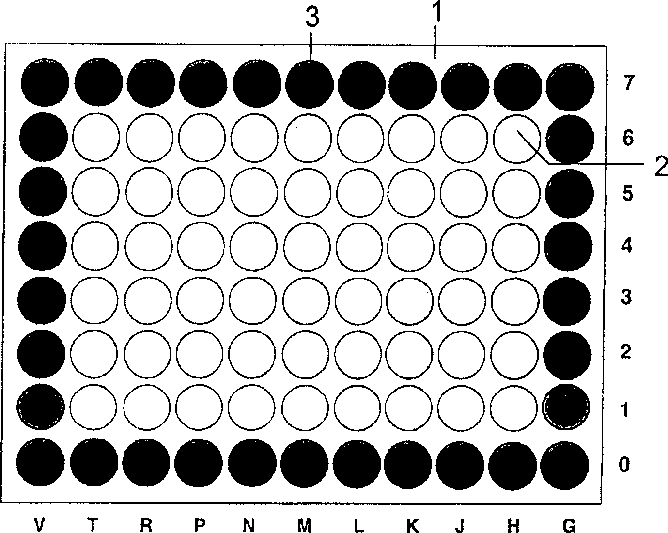
[0008] exist figure 1 , a preferred rectangular component or module 1 is shown, wherein 6×9 inner pads 2 are surrounded by an outer pad region or pad ring 3 comprising four outer pad rows: 2×10+2×7 pads. The internal pads 2 are provided as common pads, which function to connect to a board with corresponding contacts, wherein each pad on a component or module enables contact with a corresponding contact on the board for use in Electrical signals are exchanged between components or modules and boards. The outer pad area or pad ring 3 constitutes the sacrificial pad area or pad ring and generally has no electrical contact function, but any pad in this pad area or pad ring can additionally be used as a test point in the production line / multiple test points, and can be connected to the detection device, where the sacrificial pad area or a single pad of the pad ring can be used as an internal test point, and in most cases, their existence is not necessary for the end user use. ...


PUM


Abstract

The present invention relates to a method and a device for protection of a component or a module, which method and device even would be able to increase the mechanical lifetime of the component or the module. A connectivity from a module to a board is ordinary achieved with pads as via Land Grid Array (LGA), where an inner area of the module is provided with pads designated for electrical connectivity to corresponding points of connection on the board. To protect the component or the module and to increase the mecahnical life time of the component or the module, the outer area of the component or the module (1) is provided with a peripheral outer line of pads forming a sacrifice pad area or pad ring (3), where individual pad or pads can be sacrificed without destroying the inner pads (2), which are designated for the electrical connectivity to corresponding points of connection on the board provided inside the sacrifice pad area or pad ring on the component or the module.

Description

technical field [0001] The present invention relates to a method and a device for protecting a component or a module, which even make it possible to increase the mechanical life of the component or module. Communication from the module to the board is typically via pads, such as via a Land Grid Array (LGA), where the inner area of ​​the module is provided with pads designated for electrical communication to corresponding connection points on the board. Background technique [0002] Communication from the module to the board is typically through pads on the module that are placed in contact with wires or contacts on the board when the module is mounted on the board. Connected pads are difficult to inspect and even difficult to determine or estimate the mechanical life of the module with respect to the pads. Contents of the invention [0003] In order to protect the component or module, and increase the mechanical life of the comp...

Claims


Application Information

Patent Timeline
Patent Type & Authority Applications(China)
IPC IPC(8): H05K1/00H05K7/02H01L23/00H01L23/498H05K1/02H05K3/34
CPCH05K1/0218H01L23/49816H01L23/562H05K3/3436H05K2201/09781H01L2924/0002Y10T29/4913Y10T29/49147Y02P70/50H01L2924/00H05K1/02
Inventor R·华莱士J·D·麦唐纳
Owner INFINEON TECH AG
Why Eureka
Try Eureka