

A tool, a cutting insert, a shim and use of the cutting insert
A technology for cutting blades and cutting tools, which is applied in the direction of cutting blades, accessories of toolholders, and tools used in lathes, etc., and can solve problems such as static instability of support points
- Summary
- Abstract
- Description
- Claims
- Application Information
AI Technical Summary
Problems solved by technology
Method used
Image

Examples
Embodiment Construction
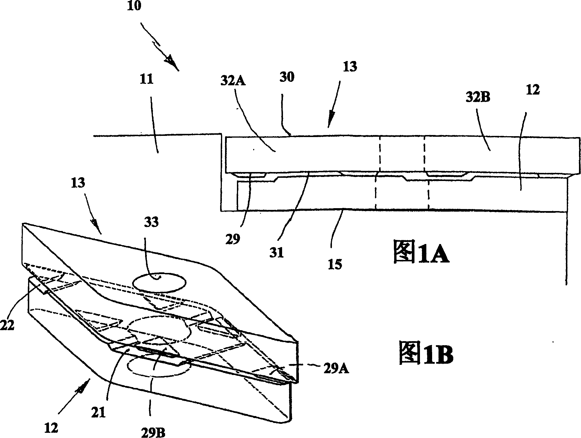
[0016] The tool 10 shown in FIGS. 1A and 1B comprises a tool holder 11 for turning or milling, a spacer 12 and an indexable cutting insert 13 made of cemented carbide. The cutting insert 13 and the spacer comprise through holes so that they can be firmly fixed against the tool holder in a conventional manner by means of screws not shown here. Alternatively, conventional clamps can also be used.
[0017] The knife holder 11 may be a square knife handle, and has a recess for mounting a spacer. The recess comprises at least two raised shoulders against which the edge surface of the cutting insert can abut.
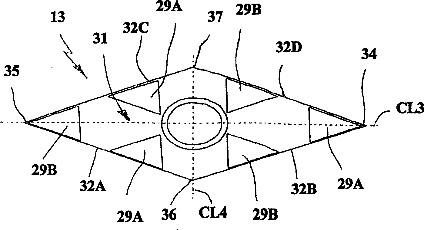
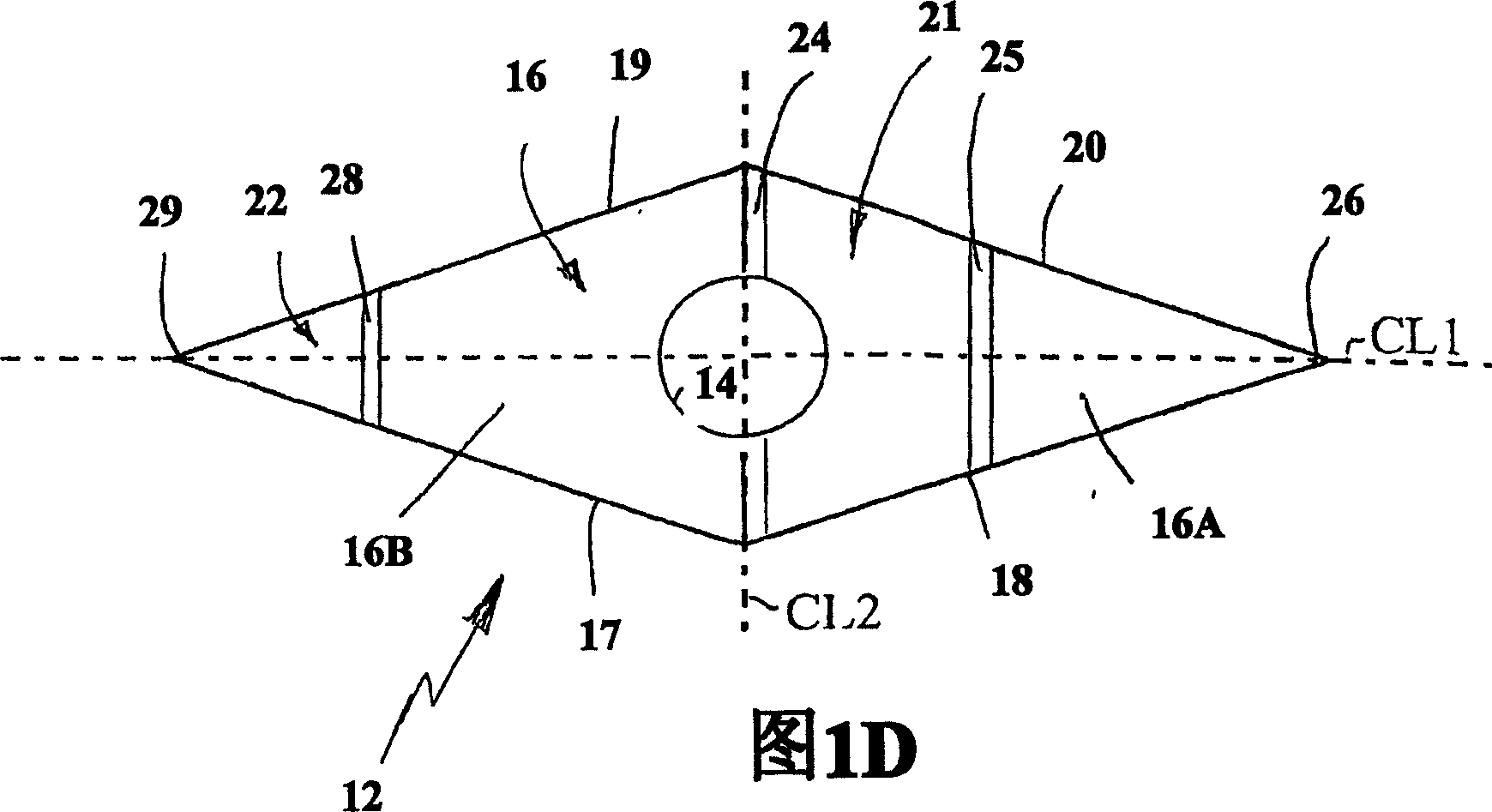
[0018] The spacer 12 has a substantially rhomboid basic shape with an imaginary major axis CL1 and an imaginary minor axis CL2. Here "rhomboid" means an oblique equilateral parallelogram. The axes or diagonals are perpendicular to each other. The major axis corresponds to the angle bisector of acute corners in a rhombus, while the minor axis corresponds to the angle bisec...
PUM
 Abstract
Description
Claims
Application Information