

Double swirl-flow combustion apparatus for industrial boiler and kiln
A technology for industrial boilers and combustion devices, which is applied to combustion equipment, solid fuel combustion, lighting and heating equipment, etc., can solve the problems of energy waste, environmental protection benefits cannot balance economic waste and energy waste, etc.
- Summary
- Abstract
- Description
- Claims
- Application Information
AI Technical Summary
Problems solved by technology
Method used
Image

Examples
Embodiment Construction
[0089] The present invention will be further described in conjunction with the accompanying drawings of the above-mentioned embodiments.
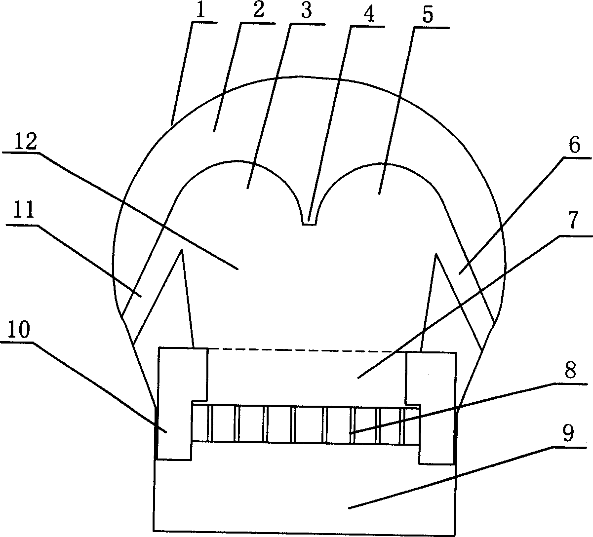
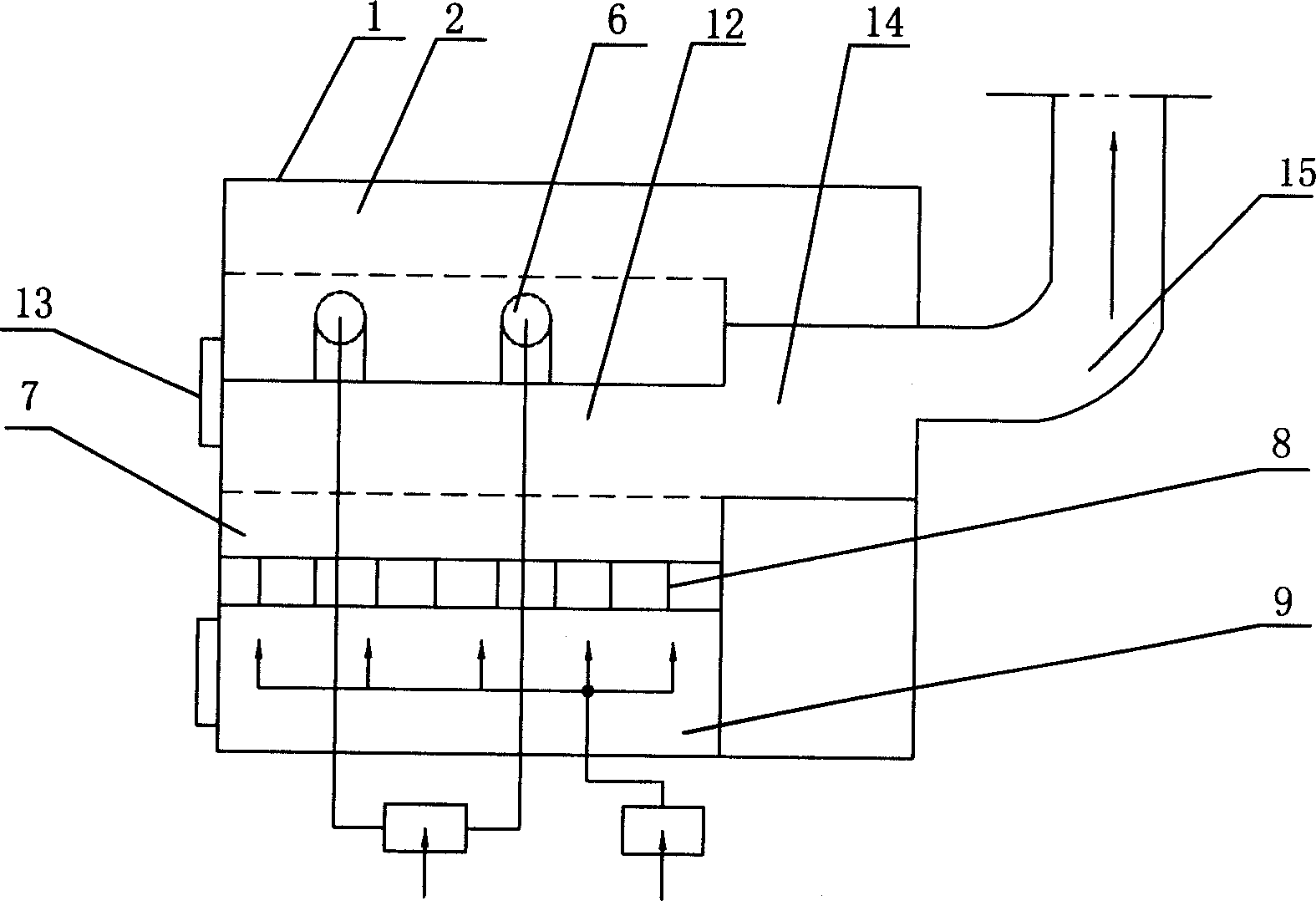
[0090] Such as figure 1 , 3 Shown, the industrial boiler of the present invention, kiln double swirl combustion device, comprise combustion hearth 12, fire grate 8, coal inlet 13 and high-temperature gas outlet 15, the top of its furnace hearth 12 cross-sections is to form double swirl The semicircle and double arches of the flow combustion areas 3 and 5 are equipped with tubular combustion air outlets 11 and 6 leading to the furnace on both sides of the furnace. A turbulent combustion zone 14 is provided between the high-temperature gas outlet 15 .
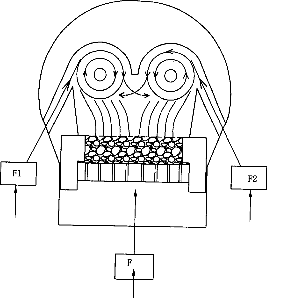
[0091] The working principle is as follows: figure 2 As shown, during the combustion operation, the combustion-supporting air is tangentially injected into the two swirl combustion zones from the combustion-supporting tuyeres 11 and 6 on both sides of the furnace at a certain speed, and th...
PUM
 Abstract
Description
Claims
Application Information