
Ultrasonic probe and ultrasonic diagnostic apparatus

A diagnostic device, ultrasonic technology, applied in ultrasonic/sonic/infrasonic diagnosis, acoustic diagnosis, infrasonic diagnosis, etc. It can solve the problems of miniaturization of the cooling system, poor energy efficiency, and larger cooling system that are difficult to satisfy the cooling capacity at the same time, and achieve Achieve cooling efficiency and operability, ensure cooling capacity, and achieve sufficient cooling capacity

Inactive Publication Date: 2006-05-03
TOSHIBA MEDICAL SYST CORP
View PDF2 Cites 28 Cited by
  • Summary
  • Abstract
  • Description
  • Claims
  • Application Information

AI Technical Summary

Problems solved by technology

When the pump for circulating the refrigerant, the radiator, and the storage window for the refrigerant are stored inside the probe connector, if a large radiator is stored in the probe connector, the size of the probe connector will increase a lot of
In addition, it is necessary to build a pump for circulating the cooling medium, a heat sink for the cooling medium, and a radiator fan for exothermic cooling in the probe connector part, which increases the size of the probe connector part.
In this way, since the cooling system will become larger if the cooling capacity is increased, it is difficult to satisfy both the improvement of the cooling capacity and the miniaturization of the cooling system.
[0018] In addition, in the case of cooling the ultrasonic probe using the conventional cooling system, the ultrasonic probe is cooled more than necessary even when the temperature of the probe part does not rise, so there is also a problem of poor energy efficiency.

Method used


Image

  • Ultrasonic probe and ultrasonic diagnostic apparatus
  • Ultrasonic probe and ultrasonic diagnostic apparatus
  • Ultrasonic probe and ultrasonic diagnostic apparatus

Examples


no. 2 Embodiment approach

[0096] Below, refer to Figure 4 An example of the cable portion in the ultrasonic probe according to the second embodiment of the present invention will be described.

[0097] Figure 4 It is a sectional view showing the cable portion of the ultrasonic probe according to the second embodiment of the present invention. Figure 4 The ultrasonic probe of the second embodiment shown and figure 2 The ultrasonic probe of the first embodiment is different in that the refrigerant pipe portion is replaced with a porous pipe having four independent holes in the longitudinal direction.

[0098] The cable portion 2b has a circular cross section, and a porous tube 22b having a circular cross section is disposed near the center of the cross section. In addition, the perforated tube 22b is made of a soft material with high heat insulation properties such as silicone rubber and soft vinyl chloride resin, and forms two refrigerant supply flow paths 22b1 and refrigerant discharge flow path...

no. 3 Embodiment approach

[0103] Below, refer to Figure 5 An ultrasonic probe according to a third embodiment of the present invention will be described.

[0104] Figure 5 It is a sectional view showing the cable portion of the ultrasonic probe according to the third embodiment of the present invention. Figure 5 The ultrasonic probe of the third embodiment shown and figure 2 The ultrasonic probe of the first embodiment is different in that the refrigerant discharge pipe is provided away from the center of the cable part.

[0105] The cross section of the cable portion 2c is circular, and the refrigerant supply pipe 23c is disposed near the center of the cross section. A plurality of signal lines 21 are arranged on the outer periphery of the refrigerant supply pipe 23 c, and shielded wires 26 of the signal lines 21 are arranged on the outer periphery of the signal lines 21 . In addition, the shielded wire 26 is covered with a clad wire 27 for insulation, protection, and the like.

[0106] Three...


PUM


Abstract

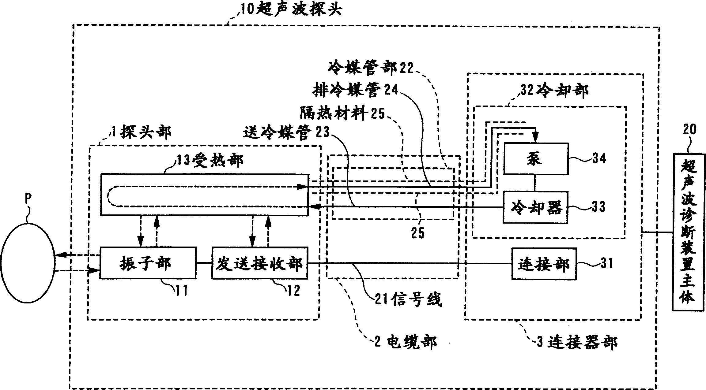
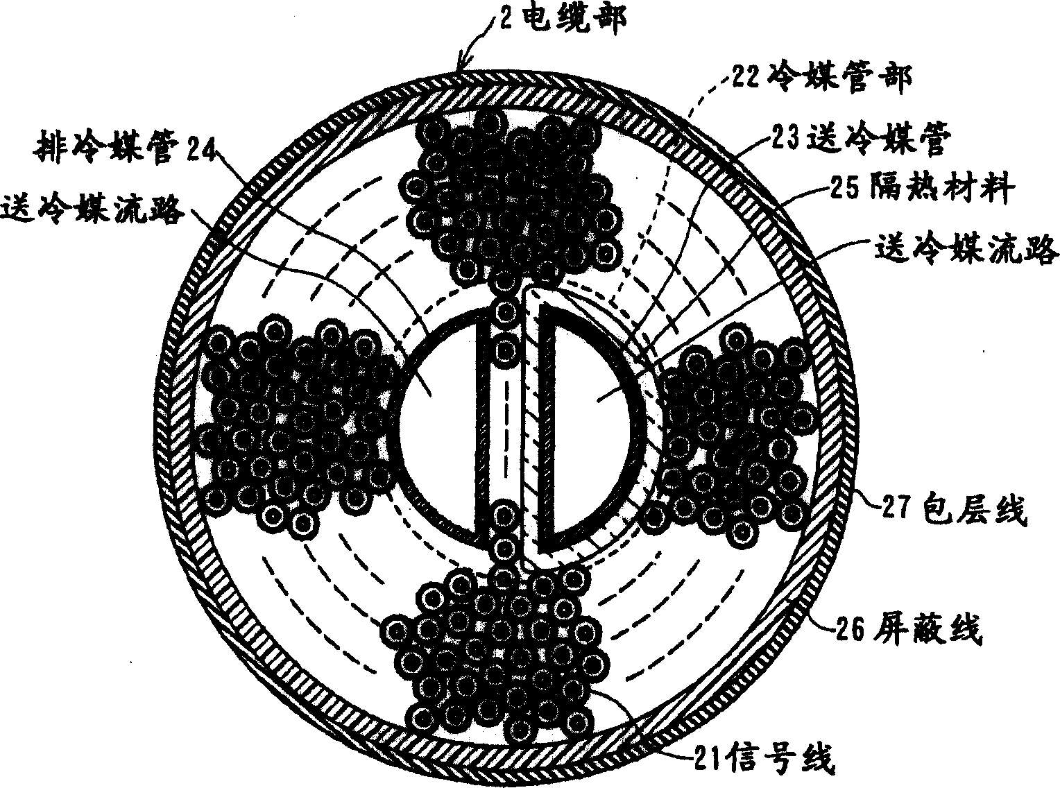
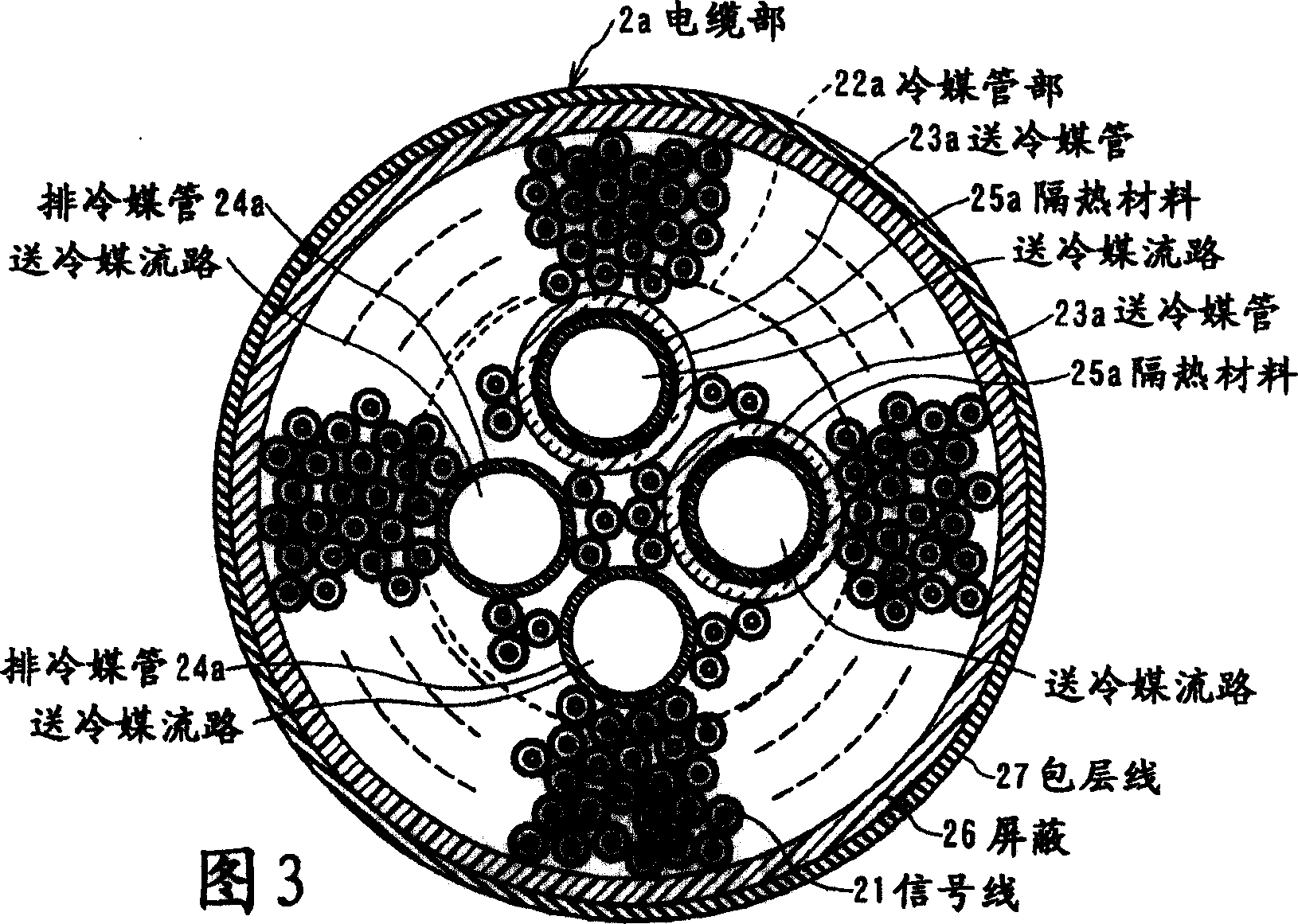
The present invention provides an ultrasonic probe including a vibrator unit, a heat receiving unit, a cooling unit, and a cable unit, and an ultrasonic diagnostic apparatus. The cable part has signal lines, refrigerant supply pipes, refrigerant discharge pipes and heat insulation materials. The heat receiving portion absorbs heat generated from the vibrator portion. The refrigerant supply pipe transports the refrigerant from the cooling unit to the heating part. The refrigerant discharge pipe transports the refrigerant that discharges the heat of the heat receiving part to the cooling unit. The heat insulating material is provided on the outer periphery of the refrigerant supply pipe. The set of the refrigerant supply pipe, the refrigerant discharge pipe, and the heat insulating material is arranged substantially at the center of the cable portion, and the signal line is arranged around at least one of the refrigerant supply pipe, the refrigerant discharge pipe, and the heat insulating material.

Description

technical field [0001] The present invention relates to an ultrasonic probe and an ultrasonic diagnostic device, in particular to an ultrasonic probe and an ultrasonic diagnostic device equipped with a cooling mechanism. Background technique [0002] An ultrasonic diagnostic apparatus that transmits ultrasonic waves into a subject and uses the reflected waves to examine the subject is widely used in the medical field. In addition, an ultrasonic probe that transmits and receives ultrasonic waves using its distal end in contact with a subject includes a plurality of transducers that convert received ultrasonic waves into electrical signals while generating ultrasonic waves. [0003] However, in terms of the operating state of the ultrasonic diagnostic apparatus, all the ultrasonic waves generated in the ultrasonic probe are not transmitted into the subject through ultrasonic transmission, but a part thereof is converted into heat absorbed by the vibrator. In addition, in the ...

Claims


Application Information

Patent Timeline
Patent Type & Authority Applications(China)
IPC IPC(8): A61B8/00G01N29/24
CPCA61B8/546
Inventor 桥本新一
Owner TOSHIBA MEDICAL SYST CORP
Learn More