Air conditioner
A technology for air conditioners and air filters, applied in air conditioning systems, external electrostatic separators, space heating and ventilation, etc., can solve the problems of inability to achieve dust collection performance and high air flow resistance
- Summary
- Abstract
- Description
- Claims
- Application Information
AI Technical Summary
Problems solved by technology
Method used
Image
Examples
Embodiment 1
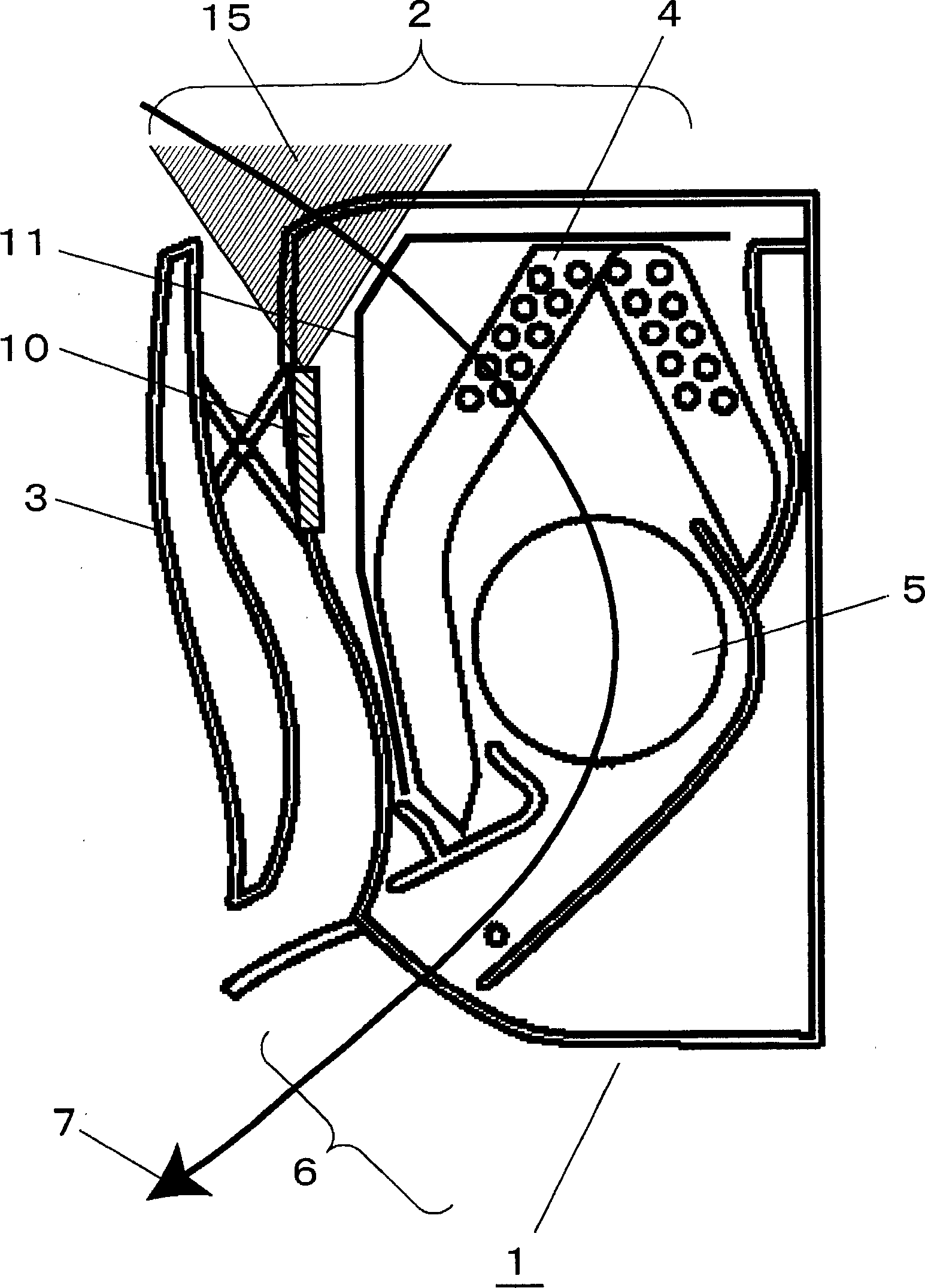
[0034] first pass figure 1 and figure 2 The first embodiment will be described.
[0035] figure 1 A schematic cross-sectional view of the air conditioner indoor unit 1 equipped with the electronic dust collection unit 10 in the first embodiment of the present invention is shown in .
[0036] figure 1 Among them, 1 is the indoor unit of the air conditioner, 2 is the suction port, 3 is the suction port baffle, 4 is the heat exchanger, 5 is the blower fan, 6 is the exhaust port, 7 is the air flow path, and 10 is Electronic dust collection unit, 11 is a pre-filter.
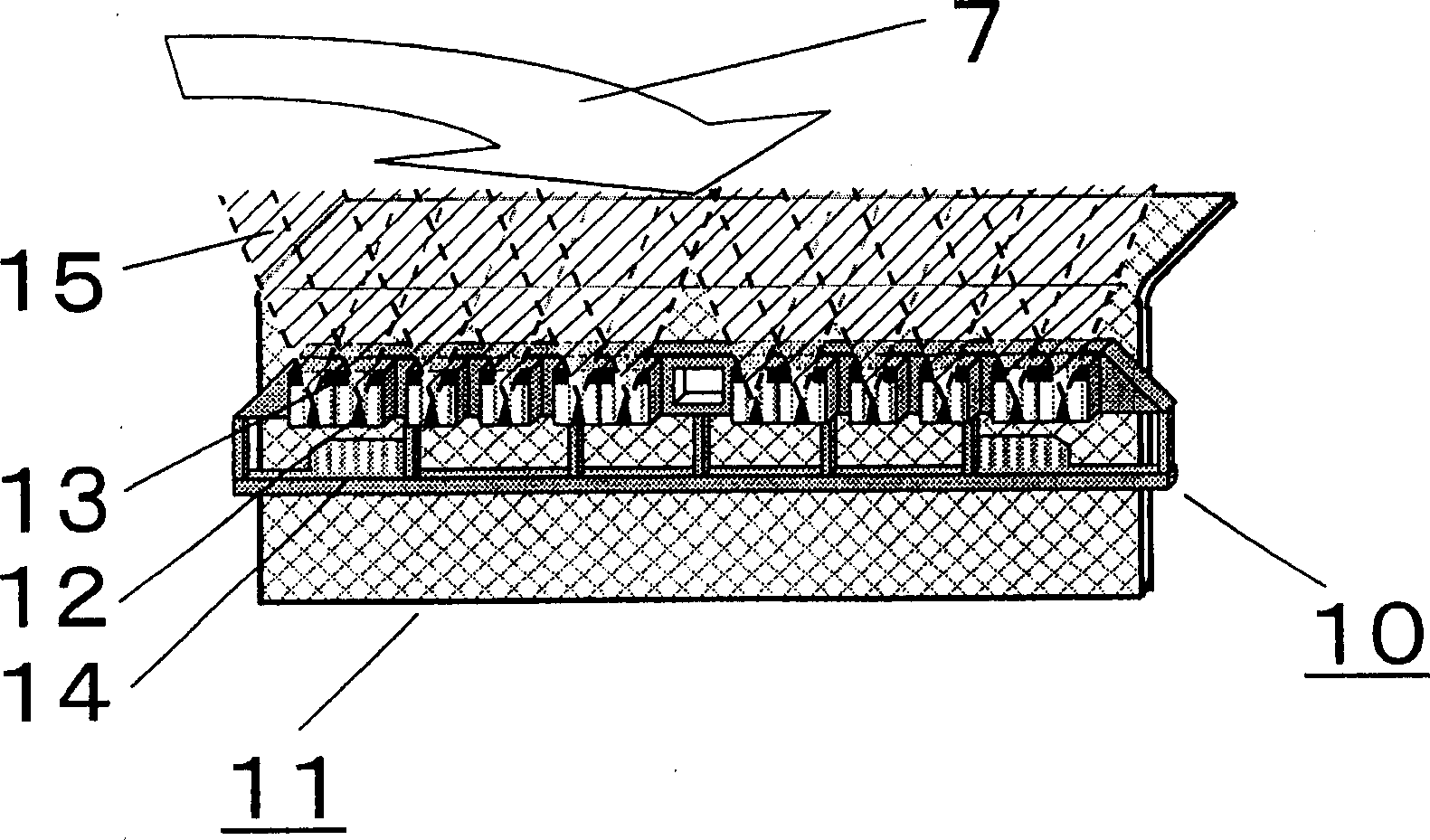
[0037] figure 2 It is a schematic diagram of the electronic dust collecting unit 10 in the first embodiment of the present invention.
[0038] figure 2 Among them, 12 is the needle-shaped discharge electrode, 13 is the ground electrode, 14 is the outer frame, and 15 is the electric field generated by the discharge area.
[0039] In the indoor unit 1 of the air conditioner, the indoor air inhaled by the air...
Embodiment 2
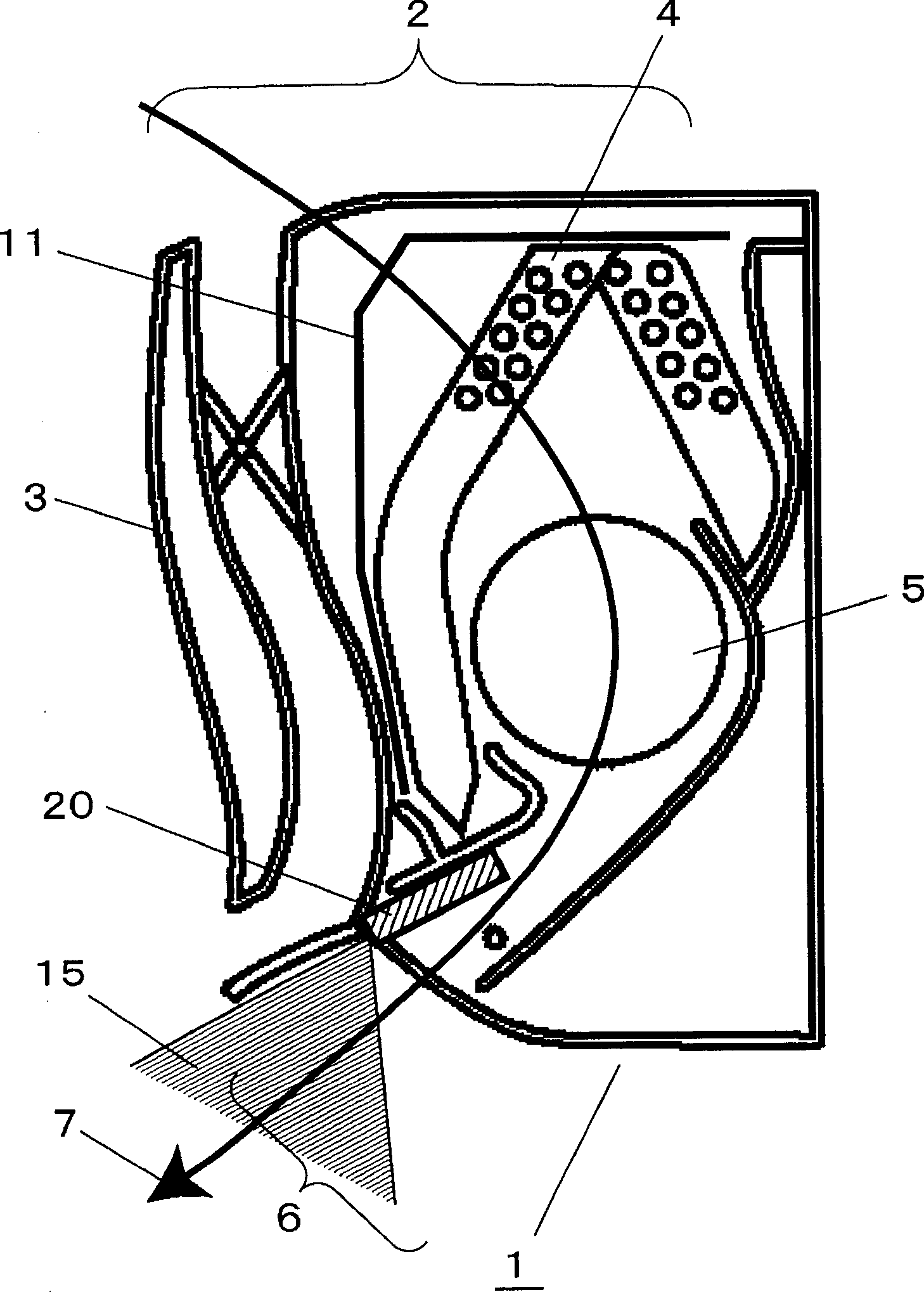
[0047] pass below image 3 Now, the second embodiment will be described.
[0048] image 3 It is a schematic cross-sectional view of the indoor unit 1 of the air conditioner equipped with the electronic dust collection unit 20 in the second embodiment of the present invention.
[0049] Wherein, the same components as those in the previous embodiment are marked with the same symbols, and repeated description thereof will be omitted.
[0050] image 3 Among them, the electronic dust collection unit 20 is arranged on the exhaust 6 of the indoor unit 1 of the air conditioner, and the air blown into the room from the exhaust port 6 passes through the electric field generated by the electronic dust collection unit 10 on the exhaust port 6. In zone 15, the oxygen and moisture contained in the air are charged and sent to the indoor space. The charged oxygen and moisture released into the indoor space will contact and combine with the floating dust in the indoor air, so that the du...
Embodiment 3
[0053] pass below Figure 4 The third embodiment will be described.
[0054] Figure 4 It is a schematic diagram of the appearance of the pre-filter 11 in the third embodiment of the present invention.
[0055] Figure 4 Among them, 30 is a conductive resin fiber. In addition, the same components as those in the previous embodiments are assigned the same symbols, and detailed descriptions thereof are omitted.
[0056] The mainstream structure of the existing pre-filter is to weave PP resin and PET resin fibers with a thickness of about 200 microns, and fix them with a frame made of resin around them. In contrast to this, in the pre-filter 11 of the present invention, the fiber diameter of the PET fiber is thinned to about 70-80 microns, and the weaving density is increased, so that the opening ratio of the filter remains constant and the air flow The fineness of the mesh can be achieved under the condition of constant resistance. Furthermore, the conductive resin fibers ...
PUM
 Abstract
Description
Claims
Application Information
 - R&D
- Intellectual Property
- Life Sciences
- Materials
- Tech Scout
- Unparalleled Data Quality
- Higher Quality Content
- 60% Fewer Hallucinations
Browse by: Latest US Patents, China's latest patents, Technical Efficacy Thesaurus, Application Domain, Technology Topic, Popular Technical Reports.
© 2025 PatSnap. All rights reserved.Legal|Privacy policy|Modern Slavery Act Transparency Statement|Sitemap|About US| Contact US: help@patsnap.com


