Electrohydraulic servo pressure-torque coupling three-way vibration loading tree-axis instrument

An electro-hydraulic servo and electro-hydraulic servo valve technology, which is applied to instruments, scientific instruments, measuring devices, etc., can solve the problems of difficult to achieve static and dynamic stress coupling changes, large changes in gas compression volume, and difficult to achieve automatic control, etc. Mutual interference, reduction of equipment manufacturing cost, effect of eliminating gaps

Inactive Publication Date: 2006-05-24
XIAN UNIV OF TECH
View PDF0 Cites 16 Cited by
  • Summary
  • Abstract
  • Description
  • Claims
  • Application Information

AI Technical Summary

Problems solved by technology

There are two major disadvantages in the force transmission mechanism system of this device. One is that when the axial direction and the horizontal plane torsion in the torsion mechanism move back and forth at the same time, the rack has no axial movement, and the gear has axial movement due to the coaxiality with the axially loaded main shaft. Therefore, there is an axial relative displacement between the rack and the gear, causing the two-way motion to affect each other; at the moment of torsion and vertical back-and-forth changes, the gap between the rack and the gear will significantly affect the waveform of the cyclic load, such as Waveform jitter is generated; the second is that the lateral loading mechanism of the inner and outer chambers uses an air pressure source. Due to the large change in the compressed volume of the gas, on the one hand, the pressure level is low, and it is difficult to realize automatic control during the dynamic process. On the other hand, due to the inner and outer chambers The lateral pressure remains constant, and it is difficult to achieve static and dynamic stress coupling changes
In addition, the device requires a complex gas-liquid conversion system, which increases the manufacturing cost of the equipment in vain

Method used


Image

  • Electrohydraulic servo pressure-torque coupling three-way vibration loading tree-axis instrument
  • Electrohydraulic servo pressure-torque coupling three-way vibration loading tree-axis instrument
  • Electrohydraulic servo pressure-torque coupling three-way vibration loading tree-axis instrument

Examples


Embodiment Construction

[0024] Below in conjunction with accompanying drawing and embodiment the present invention will be described in further detail:

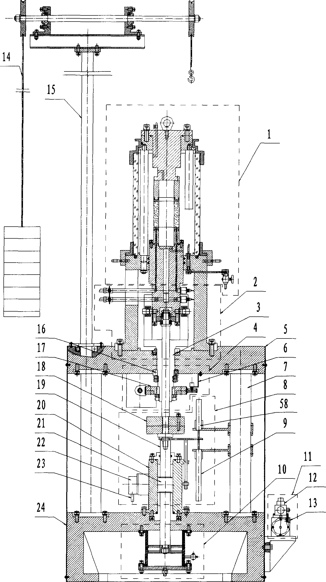
[0025] Such as figure 1 As shown, the main engine includes a pressure chamber 1 arranged on the upper part of the frame horizontal plate 5, a lifting arm 15 placed next to the pressure chamber 1 and fixed on the frame horizontal plate 5 and a lifting mechanism 14 at its upper end, and a base box 24 The upper axial pressure mechanism 8, the torsion mechanism 4 coaxially connected with the axial pressure mechanism 8, the pressure torsion connection mechanism 2 placed between the pressure chamber 1 and the torsion mechanism 4, the balance cylinder 10 placed in the base box 24 and the The lateral pressure mechanism 11 outside the base box 24; the axial pressure mechanism 8 includes a main shaft 19, an axial pressure driver 20 coaxially connected with the main shaft, and an axial pressure sensor arranged at the upper end of the axial pressure driver 20 a...


PUM


Abstract

The triaxial apparatus includes three portions: host; hydraulic power source connected to servo valve for loading electrohydraulic in three directions in host through pipe; automatic control system connected to the input signal measured by sensor as well as connected to electrical signal output from servo valve. The host includes pressure chamber, axle load mechanism, twist mechanism connected to the axle load mechanism in coaxial coupling, pressing-twisting mechanism between the pressure chamber and twist mechanism, balance-cylinder and side pressure mechanism. The balance-cylinder, side pressure mechanism and pressure chamber are connected through pipe so as to constitute self-balanced mechanism of hydraulic pressure. The invention overcomes interactional movement between axle load mechanism and twist mechanism of current triaxial apparatus of vibration and torison shear as well as overcomes disadvantages of side pressure mechanism. Features are: smooth waveform of load, and low cost.

Description

technical field [0001] The invention relates to electromechanical equipment of geotechnical engineering, in particular to a device for testing geotechnical dynamic properties. Background technique [0002] At present, the existing rock and soil dynamic properties testing equipment mainly include dynamic single shear instrument, conventional vibration triaxial instrument, resonance column instrument, vibratory torsional shear triaxial instrument. Among them, the vibrating torsional shear triaxial instrument has developed from a single application of circular torsional shear stress to a three-way vibration loading device that simultaneously applies axial cyclic normal stress, circular circular torsional shear stress and lateral static pressure stress. It can simulate more complex stress conditions, and can apply circular torsional static shear stress, axial static normal stress, internal and external cavity hydrostatic pressure, torsional cyclic shear stress and axial cyclic n...

Claims


Application Information

Patent Timeline
Patent Type & Authority Applications(China)
IPC IPC(8): G01N19/00G01N3/00
Inventor 邵生俊谢定义陈存礼刘奉银邓国华
Owner XIAN UNIV OF TECH
Why Eureka
Try Eureka