

Control system for hybrid vehicle
A control system and vehicle technology, applied in the direction of hybrid vehicles, vehicle energy storage, vehicle components, etc., can solve problems such as incoordination, and achieve the effect of preventing fluctuations and smooth shifting
- Summary
- Abstract
- Description
- Claims
- Application Information
AI Technical Summary
Problems solved by technology
Method used
Image

Examples
example 1
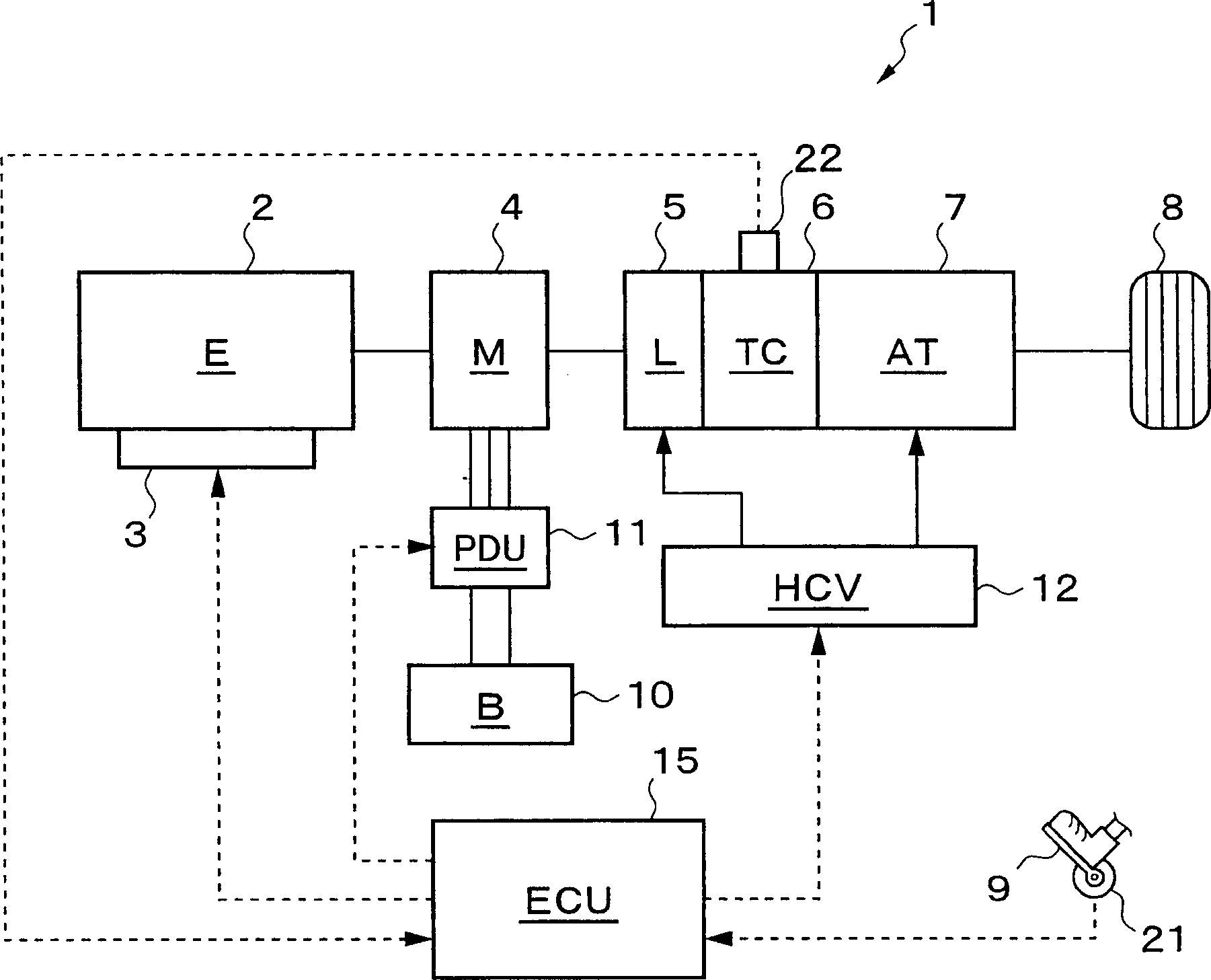
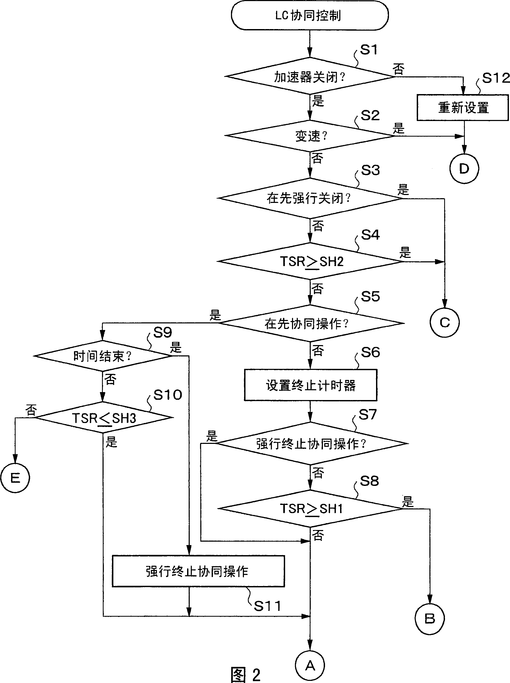
[0078] In the first example shown in FIG. 5, when it is judged that the accelerator is off at time t1, the shifting operation is not performed, and the forced release of the lockup clutch has not been performed recently. For this case, the control flow shown in FIG. 2 goes from step S1 to step S2, and from step S3 to step S4. In this case, as shown in (B), the engine speed Ne (= the torque converter input speed Nti) is greater than the transmission input shaft speed Nm (= the torque converter output speed Nto). Therefore, as shown in (C), the slip ratio TSR of the torque converter 6 is less than 100%, and TSR<SH2 (SH2=120%). As a result, the control flow goes to step S5.
[0079] Also, no co-ops have been executed recently, nor have co-ops been forcibly terminated. As a result, the flow of control proceeds from step S5 to step S6 at which the termination timer is set, and then the flow of control passes through step S7 to step S8. As described above, the slip ratio TSR is l...
example 2
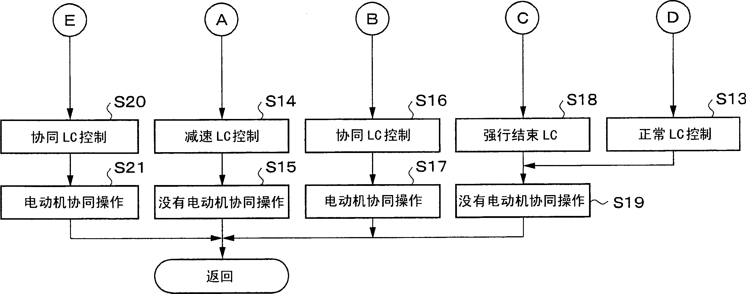
[0084] Fig. 6 shows a second example. In this example, the state at time t1 is the same as in the first example, so the control flow goes to step S14 and step S15 where deceleration lock control is started without performing cooperative operation of the motor generator 4 . As a result, the lockup clutch control pressure PLC supplied to the lockup clutch 5 increases at time t1, and thereafter, as shown in (D), the control to engage the lockup clutch 5 is started. Since the accelerator is closed, at time t2 as shown in (C), the engine speed Ne is greatly reduced beyond the transmission input shaft speed Nm, and the slip ratio TSR is increased to more than
[0085] The first threshold SH1.
[0086] Therefore, the control flow proceeds from step S8 to step S16 and further to step S17, at which the cooperative lock control is executed, and the cooperative operation of the motor generator 4 is performed. In this case, the lockup clutch control pressure PLC is lowered and adjusted ...
example 3
[0090] Fig. 7 shows a third example. Also in this example, the state at time t1 is the same as the first example, so the control flow goes to step S14 and then to step S15 where deceleration lock control is started without performing cooperative operation of the motor generator 4 . As a result, the lockup clutch control pressure PLC supplied to the lockup clutch 5 increases at time t1, and thereafter, as shown in (D), the control to engage the lockup clutch 5 is started. Since the accelerator is closed, the rotation speed of the engine greatly drops beyond the transmission input shaft rotation speed Nm, and the slip ratio TSR increases above the first threshold SH1 at time t2 as shown in (C).
[0091] Therefore, the control flow proceeds from step S8 to step S16 and further to step S17, at which the cooperative lock control is executed, and the cooperative operation of the motor generator 4 is performed. In this case, the lockup clutch control pressure PLC is lowered and adju...
PUM
 Abstract
Description
Claims
Application Information