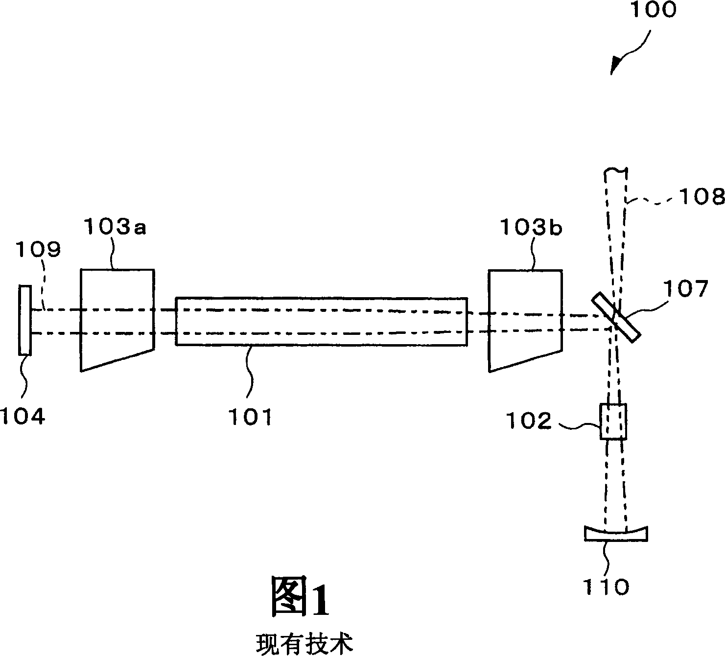
Solid-state laser generator

一种激光发生器、固态的技术,应用在激光器、声子激发器、激光器零部件等方向,能够解决不能容易增加固态激光介质数量等问题,达到高输出的效果

Inactive Publication Date: 2006-06-07
TOWA
View PDF3 Cites 7 Cited by
  • Summary
  • Abstract
  • Description
  • Claims
  • Application Information

AI Technical Summary

Problems solved by technology

For this reason, the number of solid-state laser media cannot be easily increased inside the resonator in existing solid-state laser generators employing intracavity frequency conversion

Method used


Image

  • Solid-state laser generator
  • Solid-state laser generator
  • Solid-state laser generator

Examples


Embodiment Construction

[0030] A solid-state laser generator according to an embodiment of the present invention will be described in detail below with reference to the accompanying drawings. First, a solid-state laser generator according to a first embodiment of the present invention will be described. image 3 is a diagram showing the configuration of a resonator in the solid-state laser generator of this embodiment. The solid-state laser generator of the present embodiment is a solid-state laser generator employing intracavity frequency conversion having a resonator for performing second harmonic conversion.

[0031] The resonator 10 in the solid-state laser generator of the present embodiment has: a Q switch 3a; a solid-state laser medium 1a, which is used to amplify the fundamental frequency laser 9; a Q switch 3b; a Q switch 3c; a solid-state laser medium 1b, which is used to amplify the fundamental frequency laser 9; Fundamental frequency laser 9 amplification; And Q switch 3d, they are arrang...


PUM


Abstract

Two laser media are arranged at equal intervals between a first plane mirror as a resonator mirror including a resonator and a second plane mirror for splitting laser light, the second plane mirror transmits the second harmonic laser light and reflects the fundamental frequency to the laser incident surface Laser light; a dielectric multilayer film is formed on the second plane mirror for splitting the laser light. The third plane mirror as a resonator mirror is arranged to face a direction at 90° to the incident direction of the fundamental-frequency laser light in the second plane mirror. The first lens, the nonlinear optical crystal for converting the fundamental frequency laser into the second harmonic laser, and the second lens are sequentially arranged in a single row at intervals equal to the focal lengths f of the first and second lenses between the second and second lenses. between the third plane mirrors. Thus, a space for accommodating a nonlinear optical crystal and a mirror for separating second harmonic laser light can be secured while maintaining a stable resonance condition, and the output of a solid-state laser generator can be increased.

Description

technical field [0001] The present invention relates to a solid-state laser generator employing intracavity frequency conversion, and more particularly to a solid-state laser generator whose frequency is converted by using nonlinear optical crystals. Background technique [0002] Nd:YAG lasers or other solid-state laser generators are widely used as machining lasers. Recently, the output of solid-state laser generators has increased rapidly from hundreds of watts to thousands of watts, and the application field of lasers has correspondingly expanded from the existing field of micromachining to welding and cutting applications in the automotive industry. However, the emission wavelength range of most solid-state laser generators is limited to the near-infrared range of about 1 μm, resulting in a disadvantage that the reflectivity for wavelengths outside the near-infrared range is high, and copper, silicon, and some Machining efficiency in other materials is poor. [0003] F...

Claims


Application Information

Patent Timeline
Patent Type & Authority Applications(China)
IPC IPC(8): H01S3/109H01S3/08H01S3/16
CPCH01S3/005H01S3/07H01S3/08072H01S3/0815H01S3/109H01S3/127H01S3/1611H01S3/1643
Inventor 森田浩之
Owner TOWA
Why Eureka
Try Eureka