
Self-illuminating element, display faceboard, method for producing display device and self-illuminating element

A technology of light-emitting elements and display panels, which is applied in the direction of electroluminescent light sources, lighting devices, electrical components, etc., can solve the problems of the critical angle becoming smaller and larger, and the light extraction efficiency cannot be improved, so as to improve the extraction efficiency and brighten the image display effect

Inactive Publication Date: 2006-06-07
SEIKO EPSON CORP
View PDF4 Cites 7 Cited by
  • Summary
  • Abstract
  • Description
  • Claims
  • Application Information

AI Technical Summary

Problems solved by technology

However, if the refractive index of the transparent panel is increased, the difference in refractive index between it and the outside air will increase, and the critical angle of light output from the transparent panel to the outside will become smaller.
Therefore, even if only a transparent panel with a refractive index higher than that of the light-emitting element is used, the light extraction efficiency cannot be improved because the amount of light extracted to the outside does not increase.

Method used


Image

  • Self-illuminating element, display faceboard, method for producing display device and self-illuminating element
  • Self-illuminating element, display faceboard, method for producing display device and self-illuminating element
  • Self-illuminating element, display faceboard, method for producing display device and self-illuminating element

Examples


Embodiment Construction

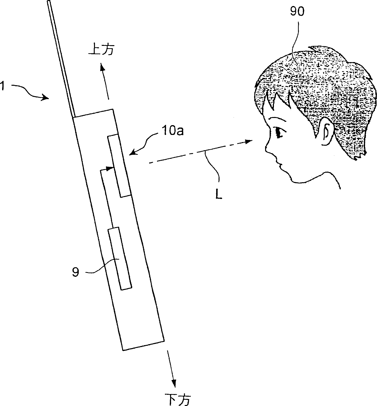
[0055] The present invention will be described in more detail below with reference to the accompanying drawings. figure 1 It is a diagram showing a mobile phone equipped with a display panel according to the present invention as a display device. In the mobile phone 1 of this example, the display panel 10a as display data is a display panel using an organic EL element of a self-luminous element, and the organic EL element emits light L by a driving device 9 composed of a microcomputer or the like, thereby Allows the user 90 to view data such as characters or images.

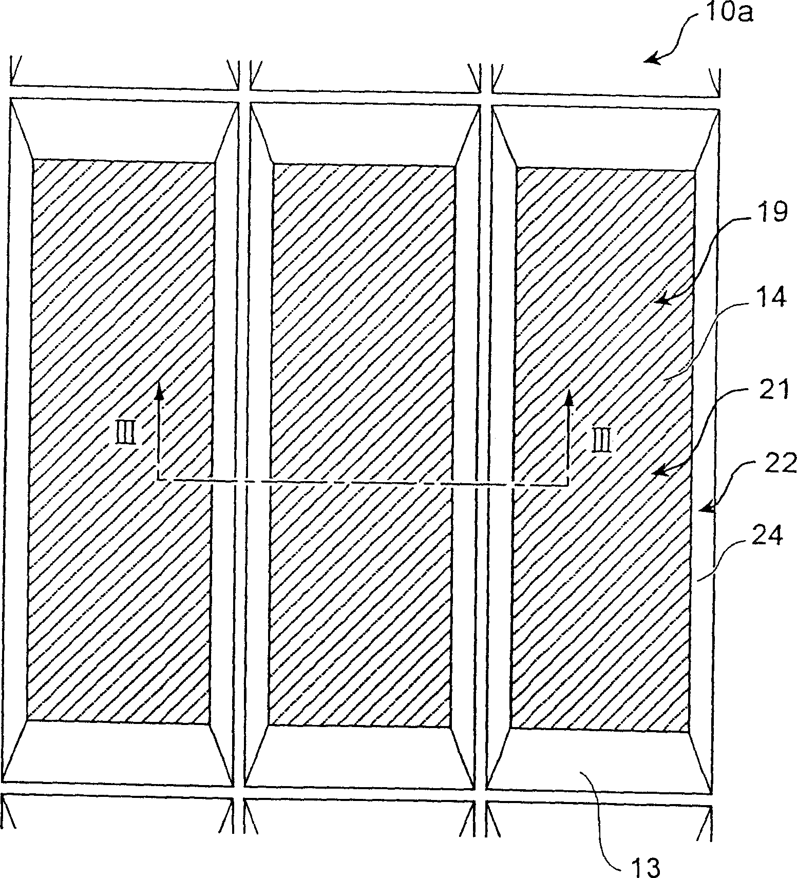
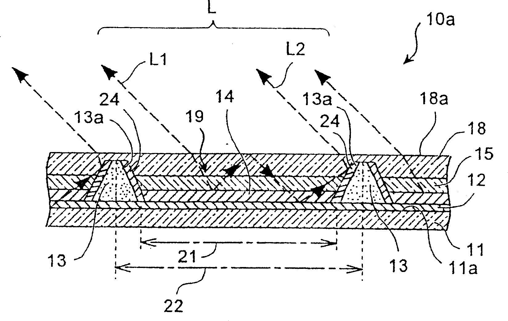
[0056] figure 2 is an enlarged plan view showing a part of the display panel, image 3 yes means figure 2Sectional view at line III-III. The display panel 10 a of this example is a panel in which a plurality of pixels composed of organic electroluminescent elements are arranged in a matrix, and can be driven by an active matrix method or a passive matrix method. The display panel 10a is composed of a singl...


PUM


Abstract

The object of the present invention is to provide a display panel with high light extraction efficiency. The provided display panel has a plurality of self-luminous elements arranged in a two-dimensional matrix, and the self-luminous elements include: a display body layer, which Comprising a light-emitting element; and a transparent output layer, the layer is located in the emission direction of the above-mentioned display body layer, and has an angle conversion part that converts the propagation direction of the output light output from the above-mentioned light-emitting element to the above-mentioned emission direction; the refraction of the above-mentioned output layer The index is the same as or greater than the refractive index of the above-mentioned light-emitting element.

Description

[0001] Cross References to Related Applications [0002] This application enjoys the priority of the Japanese patent application No. 2002-365522 filed earlier on December 17, 2002 and the Japanese patent application No. 2003-049396 filed earlier on February 26, 2003. are all included. technical field [0003] The present invention relates to a self-luminous element such as organic electroluminescence (organic EL), a display panel, a display device, and a method for manufacturing the self-luminous element. Background technique [0004] In recent years, as self-luminous flat panel displays (FPDs), display panels using organic EL elements and displays using plasma display panels (PDPs) have been developed in large numbers. These display panels are constructed by disposing a light emitting layer between an anode layer and a cathode layer. In the display panel, the self-luminous element emits light by applying a voltage between the electrodes, and characters and images can be r...

Claims


Application Information

Patent Timeline
Patent Type & Authority Applications(China)
IPC IPC(8): H05B33/00H05B33/24H01L51/50H05B33/02H05B33/04H05B33/10H05B33/12H05B33/14H05B33/22H05B33/26
Inventor 山内泰介
Owner SEIKO EPSON CORP
Learn More