Controller of permanent magnet synchronous motor

A technology for synchronous motors and control devices, which can be used in motor generator control, AC motor control, electronic commutation motor control, etc., and can solve problems such as d-axis current command value error, inability to fully weaken magnetic field control, and inability to install

Active Publication Date: 2006-06-07
MITSUBISHI ELECTRIC CORP
View PDF1 Cites 22 Cited by
  • Summary
  • Abstract
  • Description
  • Claims
  • Application Information

AI Technical Summary

Problems solved by technology

[0006] However, in the existing permanent magnet synchronous motor control device, when the DC power supply voltage of the inverter is reduced or the motor is running at high speed, etc., when the terminal voltage of the motor must be reduced, due to the The current (q-axis current) command and the motor constant include the complex calculation formula of square root and division to calculate the d-axis current command value, so there are proble...

Method used


Image

  • Controller of permanent magnet synchronous motor
  • Controller of permanent magnet synchronous motor
  • Controller of permanent magnet synchronous motor

Examples


Embodiment approach 1

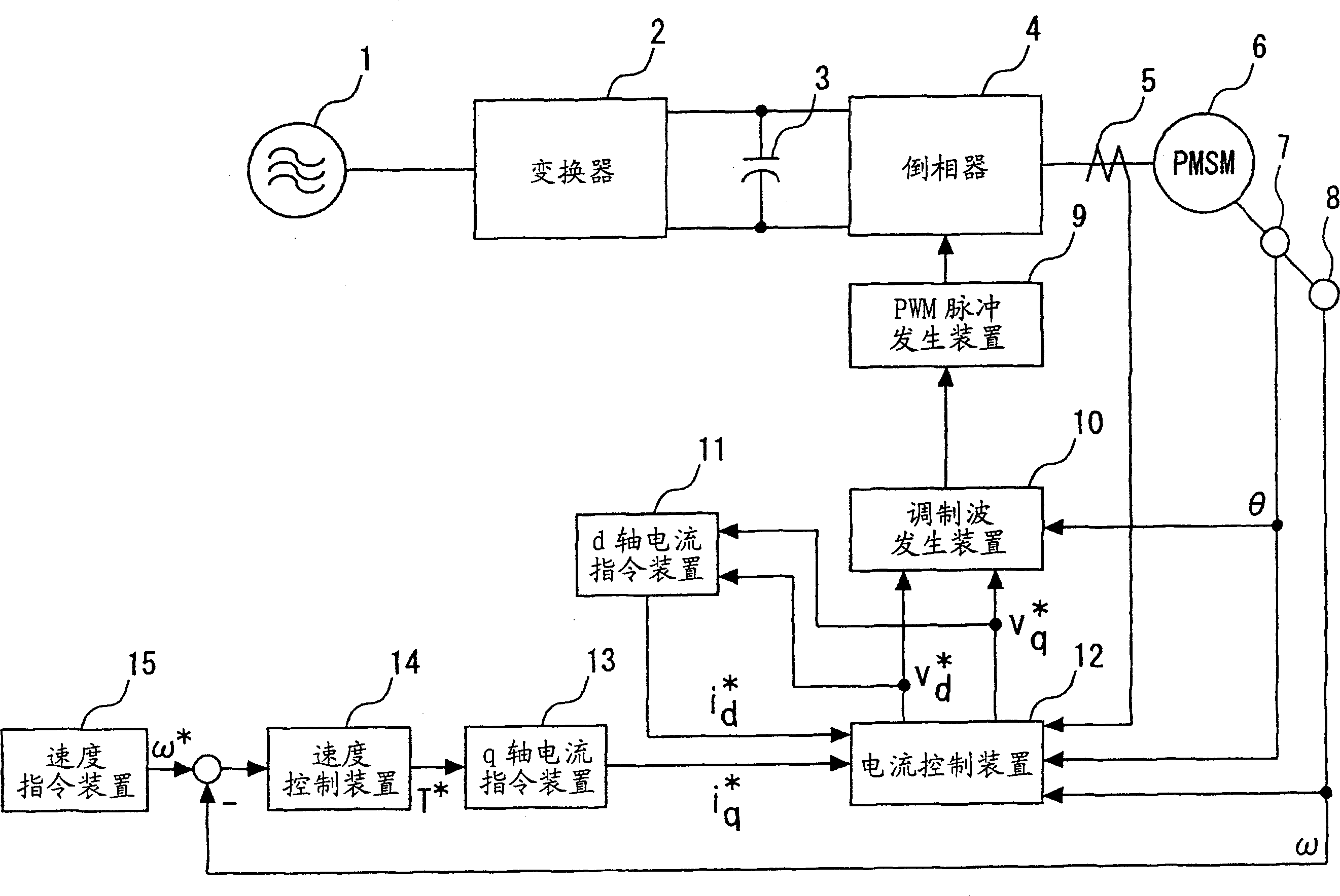
[0016] figure 1 It is a block diagram showing the control device of the permanent magnet type synchronous motor in Embodiment 1 of the present invention. In the figure, the control device of permanent magnet synchronous motor consists of AC power supply 1, converter 2, smoothing capacitor 3, inverter 4, current detector 5, permanent magnet synchronous motor 6, motor position detector 7, motor speed Detector 8 , PWM pulse generating device 9 , modulated wave generating device 10 , current control device 12 , q-axis current command device 13 , speed control device 14 and speed command device 15 constitute. AC power 1 is input into converter 2 . Converter 2 outputs a DC voltage, which is smoothed by smoothing capacitor 3 and input to inverter 4 . The inverter 4 is switched by the PWM pulse generator 9 to output a variable voltage and a variable frequency AC voltage to drive the permanent magnet synchronous motor 6 .

[0017] The motor position detector 7 and the motor speed de...

Embodiment approach 2

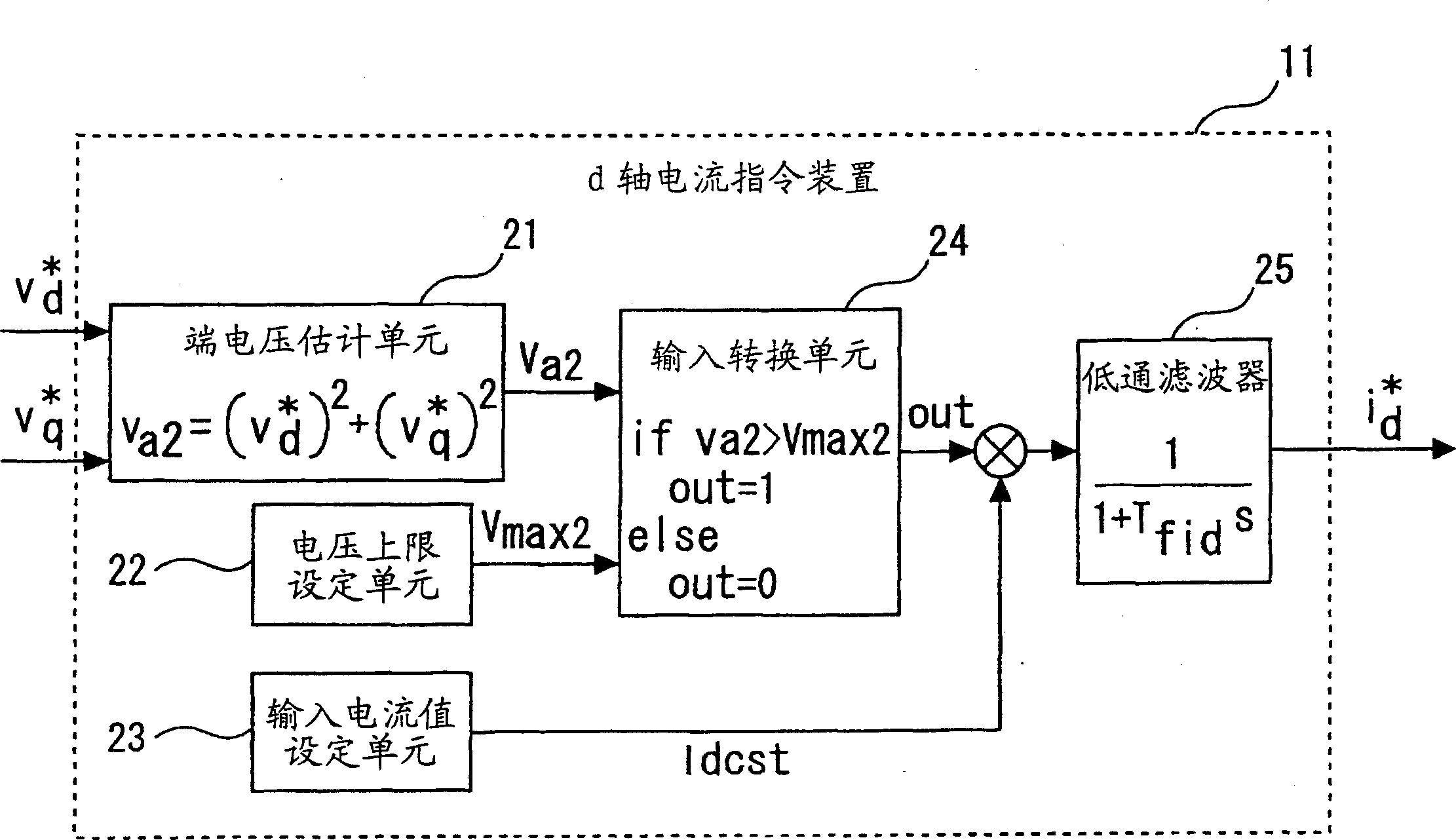
[0045] In the above Embodiment 1, as figure 2 The d-axis current command device 11 is constituted as such, but it may also be as Figure 5 With such a structure, the same operation can also be performed by such a structure.

[0046] Figure 5 It is a block diagram showing a configuration example of the d-axis current command device used in the control device of the permanent magnet type synchronous motor in Embodiment 2 of the present invention.

[0047] In Embodiment 2, instead of the input switching unit 24 for field weakening control, a current limiter 26 , an integral operation unit 27 , and an input conversion unit 28 for field weakening control having different processing contents are newly provided. again, in Figure 5 in, use with figure 2 Components denoted by the same symbols perform the same operations as those in the first embodiment.

[0048] The input switching unit 28 performing different field weakening controls compares the terminal voltage va2 estimate...


PUM


Abstract

A controller of a permanent magnet synchronous motor in which terminal voltage of the motor can be controlled with high accuracy even for a variation in motor constant through a simple arrangement without requiring square root or complex calculation expressions. Terminal voltage of the motor is controlled by feeding a negative current to d-axis such that the maximum output voltage of an inverter does not exceed the terminal voltage of the permanent magnet synchronous motor. Magnitude of the d-axis current component is regulated by comparing a voltage command value being inputted to the inverter with a terminal voltage upper limit (threshold value) being set based on the maximum output voltage of the inverter, switching the d-axis current component in the negatively increasing direction when the voltage command value exceeds the terminal voltage upper limit, and switching the d-axis current component in the negatively decreasing direction when the voltage command value does not exceed the terminal voltage. The motor is controlled such that the terminal voltage thereof does not exceed the maximum output voltage of the inverter.

Description

technical field [0001] The invention relates to a control device for a permanent magnet synchronous motor. Background technique [0002] Since the permanent magnet type synchronous motor generates induced voltage due to rotation and back electromotive force due to armature reaction, it is necessary to operate the synchronous motor so as not to exceed the maximum output voltage of the inverter. [0003] Especially when it comes to the high-speed rotation area exceeding the rated speed or the load larger than the rated torque, the terminal voltage of the motor must not exceed the maximum output voltage of the inverter. In addition, since the maximum output voltage also decreases when the DC power supply voltage of the inverter decreases, even in such a case, it must also be considered that the terminal voltage of the motor must not exceed the maximum output voltage of the inverter. [0004] As such a solution, increasing the output voltage of the inverter is also one of the m...

Claims


Application Information

Patent Timeline
IPC IPC(8): H02P21/00H02P21/06H02P21/14H02P21/18H02P21/24H02P23/14H02P23/16H02P25/026H02P27/04H02P27/06H02P27/08
CPCH02P21/0089H02P21/06H02P21/10
Inventor 酒井雅也
Owner MITSUBISHI ELECTRIC CORP
Why Eureka
Try Eureka