
Implementing method of double plane damping centrifuge speed limitnig and speed limiter and steady reducing device

A realization method, double-plane technology, applied in transportation and packaging, lifts, life-saving equipment, etc., can solve problems such as the inability to automatically adjust the descending speed, high concentricity requirements, and unstable performance, etc., to achieve safe and reliable performance, concentricity Low requirements, performance without shock effect

Inactive Publication Date: 2006-06-14
万新亮
View PDF4 Cites 7 Cited by
  • Summary
  • Abstract
  • Description
  • Claims
  • Application Information

AI Technical Summary

Problems solved by technology

[0003] Although the centrifugal speed governor patent (patent number: 200420041461.5) applied by the applicant has added a cam on the centrifugal block, the cam can push the brake shoe outwards when the centrifugal block rotates, so that it can produce several times the centrifugal force. Pressure, the reliability of the work can be guaranteed without a heavy centrifugal block, but this does not change the characteristics of its friction surface as a curved surface. In actual production, this centrifugal curved surface friction structure has high requirements for the concentricity of the components. , the processing is more difficult, the performance is not stable enough, and it is easy to produce shocks
[0004] Another typical speed-limiting technology is ZL01238423.2, ZL02275011.8 and ZL01255973.3 patents, all of which increase the friction force by setting friction plates at both ends of the sheave, but the descending speed of this structure cannot be automatically adjusted

Method used


Image

  • Implementing method of double plane damping centrifuge speed limitnig and speed limiter and steady reducing device
  • Implementing method of double plane damping centrifuge speed limitnig and speed limiter and steady reducing device
  • Implementing method of double plane damping centrifuge speed limitnig and speed limiter and steady reducing device

Examples


Embodiment Construction

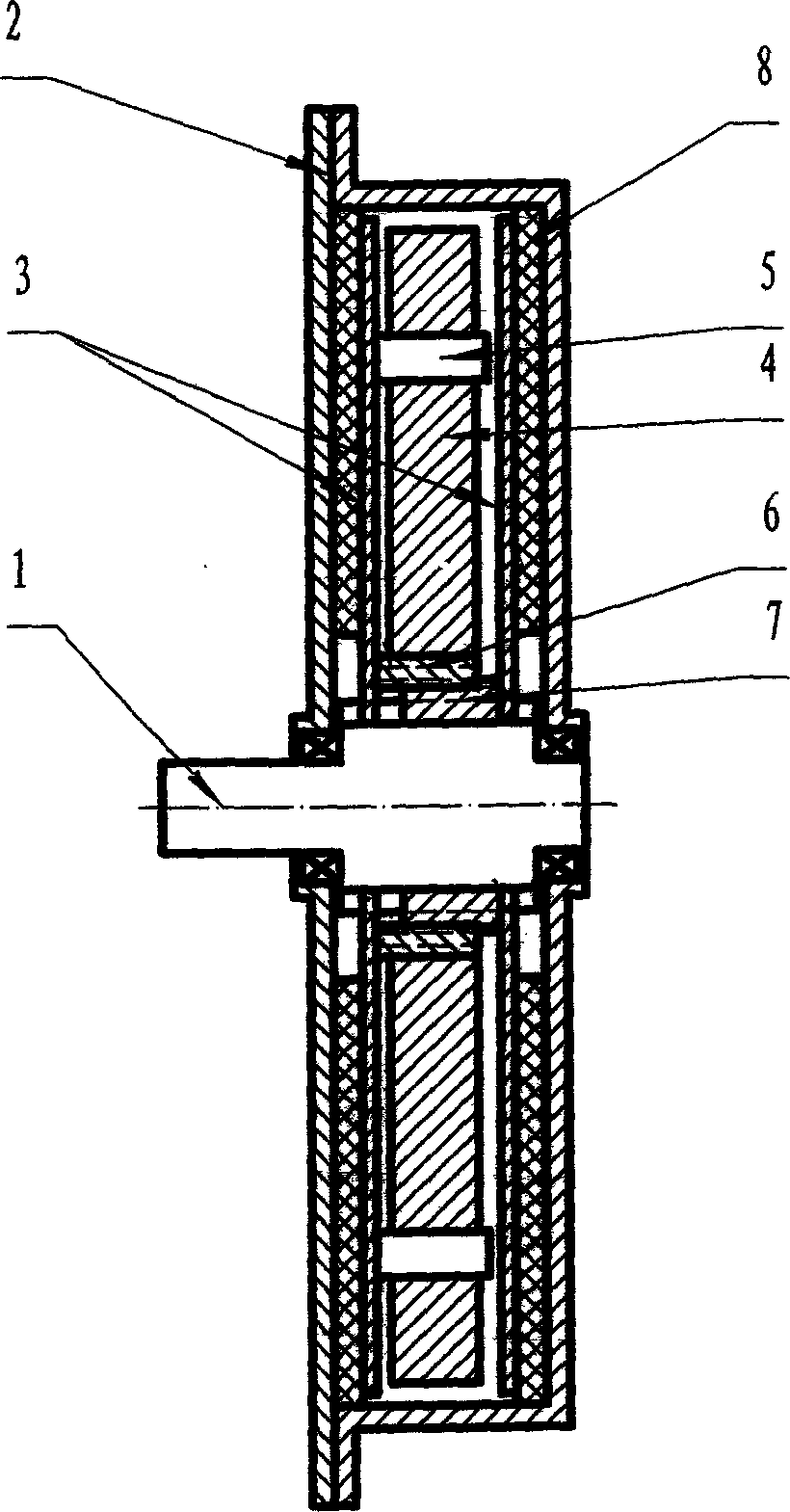
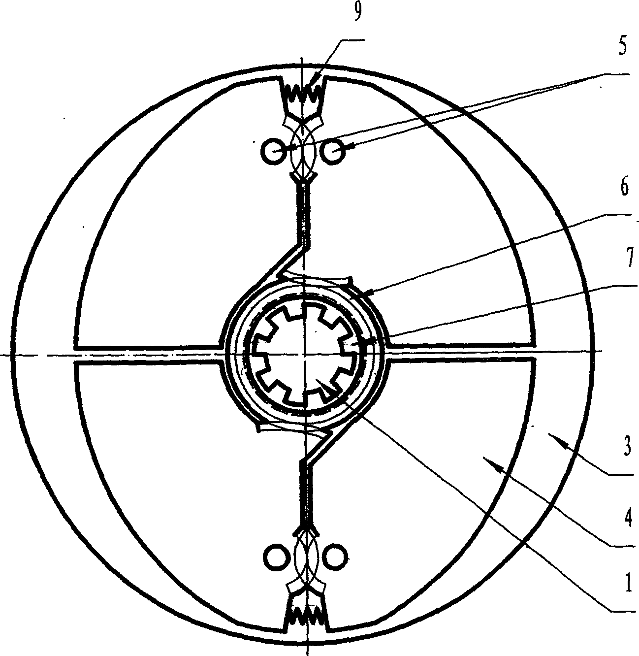
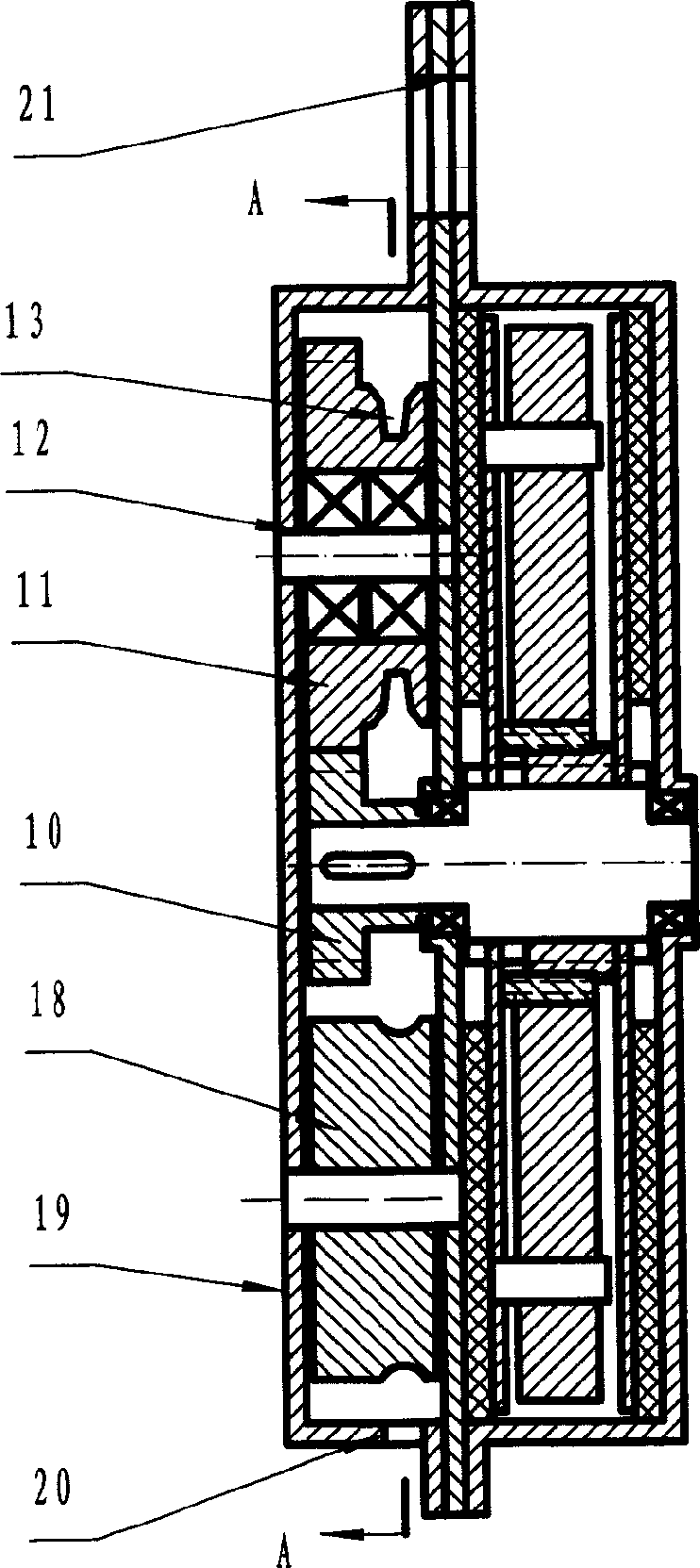
[0020] A method for realizing double-plane damping centrifugal speed limit is to use a pair of spiral sleeves on the spline shaft to engage with the centrifugal block to convert the radial centrifugal force of the centrifugal block into axial thrust, and the thrust pushes the shaft at the same time. The damping plate is pushed on its two ends and keyed on the spline shaft, so that the damping plate and the friction plate in the housing can act to obtain a double-plane damping speed-limiting torque.

[0021] A kind of double-plane damping centrifugal speed limiter designed by utilizing the method for realizing the above-mentioned double-plane damping centrifugal speed limiter, comprising a spline shaft (1) and a spline sleeve (7) sleeved on the spline shaft; the spline sleeve ( 7) There is an outer spiral sleeve (6) on the upper screw sleeve, and two damping plates (3) are arranged on the spline shaft (1) and the two ends of the spline sleeve (7), and one of the damping plates (...


PUM


Abstract

A method for implementing the dual-plane damping and centrifugal speed limitation features that a pair of spiral sleeves on spline shaft is engaged with the centrifugal block to change the radial centrifugal force of said centrifugal block to axial push force, which pushes the damping plate to act on the friction plate for obtaining the dual-plane damping force moment to limit speed. Two speed limiters and the lowering stabilizer, which are designed by said method, are also disclosed.

Description

technical field [0001] The invention belongs to the technical field of operating machinery, and specifically relates to a dual-plane damping centrifugal speed-limiting method that can eliminate the acceleration of gravity of a falling object and stabilize its deceleration within a set range, and the dual-plane damping designed using this method Centrifugal speed limiter and stabilizer. Background technique [0002] The speed limiter is a commonly used device in the field of operation technology, and the typical product used in the speed limiter is the escape and stabilization device for high buildings. With the increasing urbanization, there are more and more high-rise buildings in the city, which has caused a series of new problems. For example, the problem of self-rescue escape when running into a crisis situation (such as fire, earthquake). Although there are emergency stairs in the design of high-rise buildings, due to the large number of people in the high-rise buildi...

Claims


Application Information

Patent Timeline
IPC IPC(8): A62B3/00B66B5/04
Inventor 万新亮
Owner 万新亮
Learn More