
Method for controlling pre-aligning of silicon wafer

A control method and silicon wafer technology, applied in computer control, general control system, control/regulation system, etc., can solve problems such as great influence, low precision, and increase equipment cost, achieve measurement error suppression, improve overall Performance, easy to use effect

Inactive Publication Date: 2006-06-14
TSINGHUA UNIV
View PDF8 Cites 47 Cited by
  • Summary
  • Abstract
  • Description
  • Claims
  • Application Information

AI Technical Summary

Problems solved by technology

Although this method is used to detect cut edges, it is also applicable to the detection of gaps
The disadvantage of this method is that the size of the sampling density has a great influence on the gap (or cutting edge). The higher the sampling density, the more accurate the gap detection, and the higher the time and space complexity.
However, the correction of the trimming position in this patent only uses two points adjacent to the initial position for calculation, which is affected by the accuracy of the sampling points
US patent 6275742 proposes a cross-correlation method to solve the position of the gap, but the disadvantage of this method is that a known gap pattern is required to be compared with the sampled data
Its shortcoming lies in the calculation of the straight line, which only uses 2 points respectively, and is also affected by the sampling accuracy
[0006] 1. Mechanical center alignment Due to the contact between the contact roller and the edge of the silicon wafer, on the one hand, the silicon wafer may be polluted, and on the other hand, the roller may deform the silicon wafer during positioning
[0007] 2. Using multiple optical sensors increases equipment cost
[0008] 3. The method of detecting the center of the circle and the gap (cutting edge) is too simple and the accuracy is not high
Either multiple repeated operations are required, or only a few discrete sampling points are used, the accuracy of the calculation is greatly disturbed by the error of a single sampling point, and all the sampling data cannot be fully utilized
[0009] 4. The limitations of equipment or methods cannot be applied to the needs of the current IC process, such as only applicable to the detection of trimming or "V"-shaped notches, not suitable for the detection of arc-notched silicon wafers

Method used


Image

  • Method for controlling pre-aligning of silicon wafer
  • Method for controlling pre-aligning of silicon wafer
  • Method for controlling pre-aligning of silicon wafer

Examples


Embodiment Construction

[0033] The silicon wafer pre-alignment control method of the present invention is described in detail as follows in conjunction with embodiments and accompanying drawings:

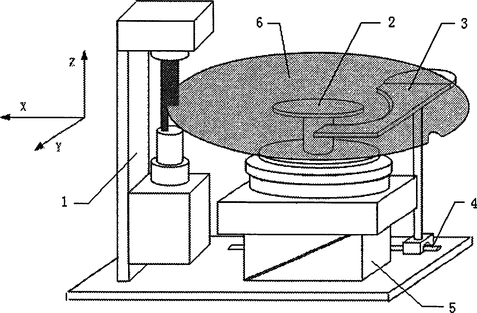
[0034] The structure of the embodiment of the silicon wafer pre-alignment equipment used in the method of the present invention is as follows figure 1 As shown, wherein, 6 is a silicon wafer with a notch (in this embodiment, an 8-inch (diameter 200mm) silicon wafer is used), 2 is a rotating unit, which can rotate around the Z axis, and the circular platform at the top has a The groove is used for vacuum adsorption of silicon wafers; 5 is a wedge-shaped platform, which can make the rotating unit 2 move along the Z direction by moving in the X direction; 3 is the centering unit, and the top of the semicircular platform also has a groove 4 is a horizontal guide rail, and the centering unit 3 can move in the X direction along the horizontal guide rail; 1 is a CCD detector (in this embodiment, the line array li...


PUM


Abstract

The invention belongs to the field of computer numerical control, especially relating to a method fro controlling silicon wafer prealignment, comprising : a silicon wafer locating method comprising circular sampling of silicon wafer, data preprocessing, circle fitting and silicon wafer centering; and a gap locating method comprising gap rough locating, gap fine sampling, gap fitting and angling the gap center. The invention can largely improve the aligning accuracy.

Description

technical field [0001] The invention belongs to the technical field of computer control, in particular to a control method for silicon wafer pre-alignment in the field of IC manufacturing. Background technique [0002] Silicon wafer pre-alignment control is one of the most important links in the IC manufacturing process. Since the field of view of the lithography machine is very small, before the silicon wafer is transferred to the lithography machine for exposure, the silicon wafer must be pre-aligned, so that the marking of the silicon wafer transferred to the exposure table is within the lithography machine's within sight. Specifically, the process of silicon wafer pre-alignment control is to use a certain method to make the center of the silicon wafer within a certain range, and at the same time, the notch of the silicon wafer stays at a specified angle, that is, including the positioning of the center of the circle and Gap detection has two main processes. [0003] T...

Claims


Application Information

Patent Timeline
IPC IPC(8): H01L21/68G03F7/20G05B15/00
Inventor 宋亦旭李世昌赵雁南杨泽红王家钦贾培发慕强
Owner TSINGHUA UNIV
Learn More