Pillow bolster for checking physiological parameter

A technology of physiological parameter detection and pillow cushion, applied in pillows, diagnostic recording/measurement, medical science, etc., can solve problems such as inappropriate hardness, complicated equipment, sleep influence, etc., to eliminate psychological influence, simple device, convenient carry effect

Inactive Publication Date: 2006-06-21
BEIJING BAOMAI TECH +1
View PDF0 Cites 35 Cited by
  • Summary
  • Abstract
  • Description
  • Claims
  • Application Information

AI Technical Summary

Problems solved by technology

However, there are problems such as complex equipment, high price, and single-person use in testing mattresses. It is only suitable for hospitals, laboratories and special populations, and is not suitable for home use.
And some types of testing mattresses, their hardness is not suitable for some people, and it will also affect sleep

Method used


Image

  • Pillow bolster for checking physiological parameter
  • Pillow bolster for checking physiological parameter
  • Pillow bolster for checking physiological parameter

Examples


Embodiment 1

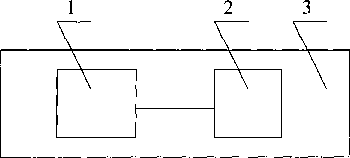
[0019] The principle of physiological parameter detection pillow is as follows: figure 1 , the high-sensitivity sheet piezoelectric micro-sensor array 1 is fixed in the interlayer of the pillow 3, the pillow is placed on the pillow or pressed under the pillow, and the head of the person rests on the pillow, the sensor array 1 will be able to feel The micro-vibration composite signal caused by human heart beating, lung activity and head activity is sent to the detection circuit 2.

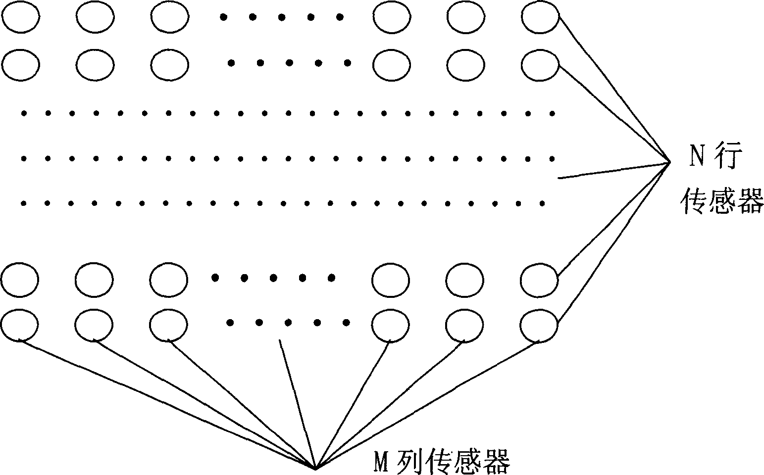
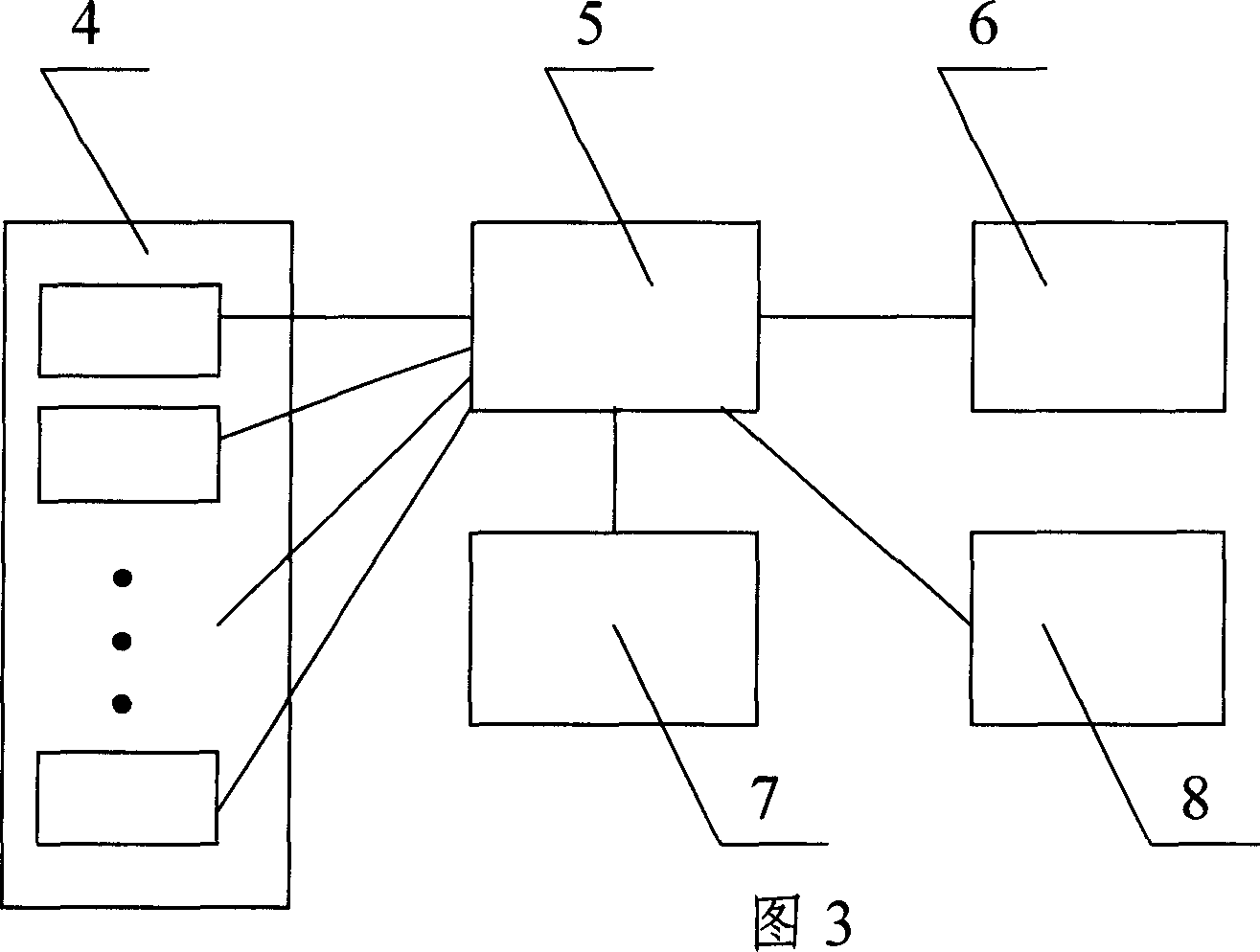
[0020] The sensor array structure of this embodiment is as follows figure 2 , in order to detect the sleeping position, each sensor has an independent output. The detection circuit is shown in Figure 3. The output signal conditioning part 4 of each sensor includes N×M signal amplification and filtering circuits. The MCU microcontroller 5 undertakes N×M data collection, processing and control functions. The storage part 6 and wireless Part 7 records and transmits signals containing cardiac and res...

Embodiment 2

[0022] This embodiment is a simplification of Embodiment 1, the structure of the sensor array is as follows figure 2 , the output of each row and column sensor in the sensor array is summed according to the row and column, and the summed signal is collected, and there are N+M signals, which can reduce the number of chips in the detection circuit and the data volume of the collected signal. When there is no need to detect the sleeping position, the outputs of all the sensors in the sensor array can be summed, and only one signal is superimposed, including heartbeat and respiration waves, and head movement signals.

Embodiment 3

[0024] This example will figure 2 The output of each row and column sensor in the sensor array is connected in parallel, and the signal after parallel connection contains cardiac and respiratory waves, and the head movement signal is amplified and collected by a single channel. This embodiment cannot detect the sleeping position, and the advantage is that not only the number of chips and the data volume of the collected signals are greatly reduced, but also the sensor array and the connection between the sensor array and the detection circuit are reduced.


PUM


Abstract

The physiological parameter detecting pillow cushion consists of one sensor array with several rows and lines of sensors, one pillow cushion bag for the sensor array to be set in, and one detection circuit inside the pillow cushion. The high sensitivity chip piezoelectric micro sensors detect compound vibration signals near head caused by the heart, the lung, the body, etc. and the sensor array may have output in different forms. The detection circuit completes treatment of signals from the sensor array, data acquisition and record, and radio transmission. The pillow cushion is set on or below the pillow to record and transmit the signals representing heart beat, breath, body motion, sleep posture and snoring. The present invention has the advantages of no disturbance on the testee, simple structure, low cost, etc. and may be used in household and other common environment, as well as hospital, lab or other special condition.

Description

technical field [0001] The invention relates to a human vital sign detection device, in particular to a physiological parameter detection pillow. Background technique [0002] Sleep is very important to human health. Some physiological parameters during sleep, such as cardiac cycle, respiratory wave, body movement, and snoring parameters, can reflect the quality of sleep. Monitoring these parameters can understand sleep and find problems in sleep, and then make corresponding improvements through different means. In order not to disturb people's sleep, the detection device preferably has no influence on people. Traditional sleep and physiological parameter detection devices used in hospitals require electrodes and sensors to be pasted on the body and connected to the instrument through wires. This method has a great impact on the sleep of the detected person, and the complex and expensive detection device is not suitable for use at home. Since the 1980s, different methods ...

Claims


Application Information

Patent Timeline
Patent Type & Authority Applications(China)
IPC IPC(8): A47G9/10A61B5/00
Inventor 吕晓东阎永华葛宏范军郭云刘威曲昕耿斌张永保
Owner BEIJING BAOMAI TECH
Why Eureka
Try Eureka