Engine camshaft

A camshaft and engine technology, applied to engine components, machines/engines, mechanical equipment, etc., to achieve the effects of reducing fuel consumption, increasing layout space, and reducing friction loss

Inactive Publication Date: 2006-06-21
CHERY AUTOMOBILE CO LTD
View PDF0 Cites 10 Cited by
  • Summary
  • Abstract
  • Description
  • Claims
  • Application Information

AI Technical Summary

Problems solved by technology

But the disadvantages of the aforementioned double overhead camshafts are unavoidable

Method used


Image

  • Engine camshaft
  • Engine camshaft
  • Engine camshaft

Examples


Embodiment Construction

[0015] The present invention will be further described below through specific embodiments and in conjunction with the accompanying drawings.

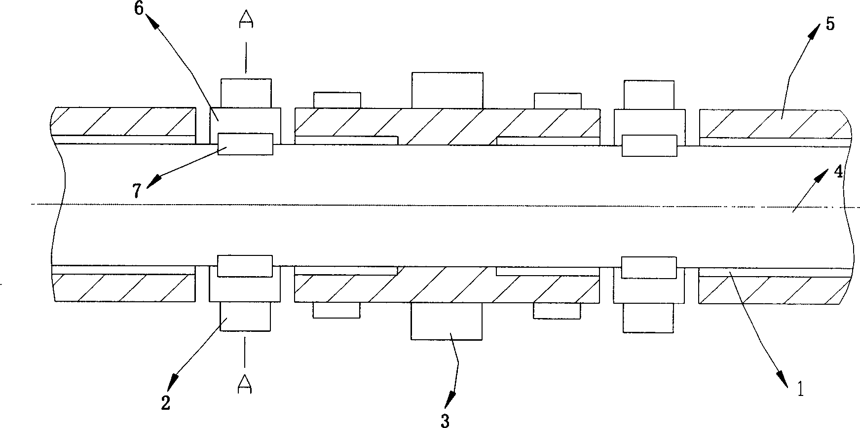
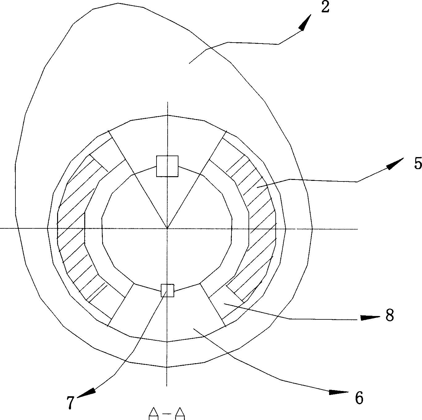
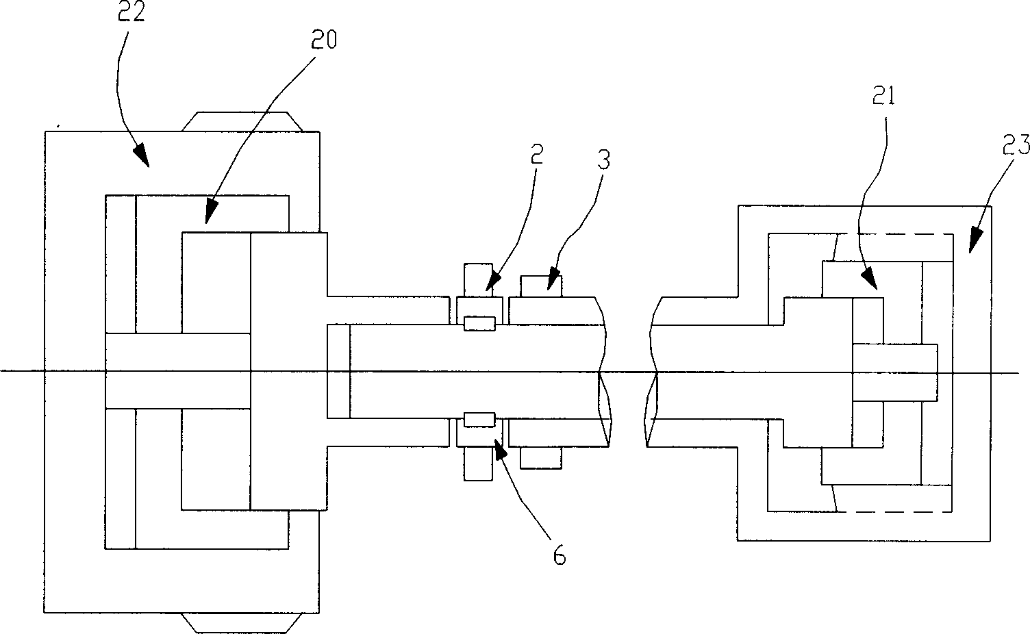
[0016] Such as figure 1 The engine camshaft includes a shaft body 1 and an intake cam 2 and an exhaust cam 3 distributed and fixedly connected to the shaft body 1. The shaft body 1 is designed in such a way that the shaft body 1 consists of inner The shaft 4 and the outer shaft 5 are composed; the intake cam 2 is fixedly connected to the inner shaft 4, and the exhaust cam 3 is fixedly connected to the outer shaft 5. Through the driving mechanism, the inner shaft 4 and the outer shaft 5 can be relatively rotated, thereby Drive the intake cam 2 and the exhaust cam 3 to move relative to each other to achieve the best gas timing.

[0017] The combined shaft body 1 has the same installation arrangement as the single overhead camshaft, but it can achieve a technical effect better than that of the single overhead camshaft, because: the combin...


PUM


Abstract

This invention relates to motor distribution structure and to provides one motor cam axle, which comprises axle part and the gas in cam axle and drainage cam axle fixed and is characterized by connecting gas in cam axle and drainage axle in same axle to move relatively. This invention can get best distribution phase angle under load of motor change to improve motor property and enlarge distribution space and to release motor weight and also it makes the motor power output smooth with less consumption power to release whole system quality to improve the motor total property.

Description

technical field [0001] The technical solution to be protected by the present invention belongs to the technical field of the gas distribution mechanism of an internal combustion engine, and specifically relates to a camshaft of an engine. Background technique [0002] The gas distribution mechanism of the engine is a mechanism to ensure that the engine regularly fills the cylinder with fresh combustible gas mixture during operation, and discharges the exhaust gas after combustion out of the cylinder in time. The camshaft is an integral part of the gas distribution mechanism of the engine. The structure of the camshaft of the engine of various models is similar, and the main difference lies in the installation position. The number and shape and size of the cams are not the same, especially the installation position of the camshaft, which is listed as an important sign to distinguish the structure and performance of the engine. At present, the cam installation positions of th...

Claims


Application Information

Patent Timeline
Patent Type & Authority Applications(China)
IPC IPC(8): F01L1/047
Inventor 辛军
Owner CHERY AUTOMOBILE CO LTD
Why Eureka
Try Eureka