Method of localizing fluorescent markers

A labeling and fluorescence radiation technology, applied in fluorescence/phosphorescence, measurement devices, material analysis through optical means, etc., can solve problems such as the inability to freely select wavelengths and limited spatial resolution

Inactive Publication Date: 2006-06-21
FEI CO
View PDF1 Cites 6 Cited by
  • Summary
  • Abstract
  • Description
  • Claims
  • Application Information

AI Technical Summary

Problems solved by technology

The employed wavelength cannot be freely chosen, since only light within the wavelength of a given band will excite a

Method used


Image

  • Method of localizing fluorescent markers
  • Method of localizing fluorescent markers
  • Method of localizing fluorescent markers

Examples


Embodiment Construction

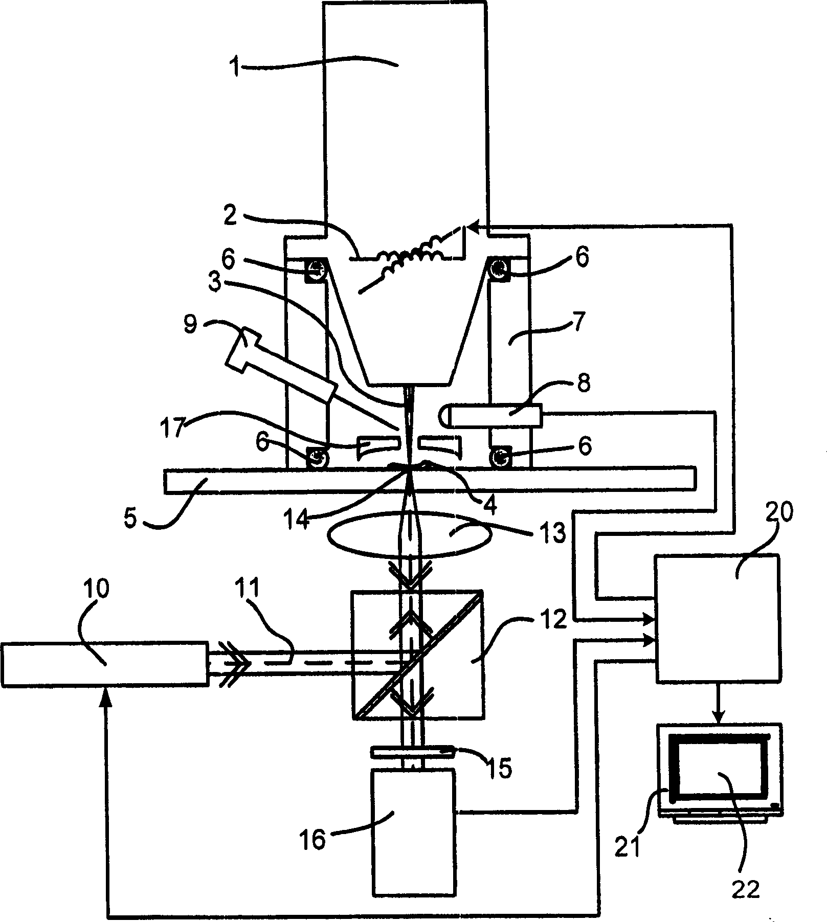
[0044] figure 1A schematic diagram of an apparatus for performing the method of the invention is shown. A particle-optical column 1 , such as an ion column, generates a focused particle beam 3 of charged particles. The particle beam 3 is focused onto a sample 4 on a sample holder 5 . A focused particle beam 3 is scanned over a sample 4 by means of a deflection unit 2 .

[0045] Charged particles (eg secondary electrons) emitted from the sample are detected by a particle detector 8 (eg Everhardt-Thornley detector).

[0046] The vacuum required to focus the particle beam 3 is obtained by sealing the vacuum chamber 7 with the aid of the sealing device 6 and then evacuating the vacuum chamber with a vacuum pump (not shown).

[0047] It should be pointed out that, in the case of biological samples, it is advantageous to maintain a small residual pressure of water vapor so that the sample does not dry out too much. This technique is a known technique and is used, for example, in...


PUM


Abstract

The present invention describes a method for determining the location of fluorescent labels in a sample (4) with high spatial resolution. For this purpose, the sample (4) is irradiated with the excitation beam (11), while the sample (4) is scanned with the particle beam (3). During scanning, the markers are collided with the particle beam (3) and destroyed so that the collided markers no longer emit fluorescent radiation. This results in a decrease in the fluorescence radiation flux. Detect this drop. Since the position of the particle beam (3) relative to the sample is known at the moment the marker is destroyed, the position of the marker in the sample can also be known.

Description

technical field [0001] The invention relates to a method for determining the position of radiation-excitable markers in a sample to be investigated, said method comprising: [0002] - set markers in the specimen; [0003] - irradiating the sample with the first radiation beam, as a result of the irradiation an excitation zone is formed in the sample, markings in the excitation zone are excited; [0004] - detection of fluorescent radiation emitted by the label in response to excitation; and [0005] - Preventing the detection of fluorescent radiation in the partial excitation region by means of the second radiation beam. [0006] The invention also relates to a device for carrying out the method. Background technique [0007] Such a method is known from US Patent No. 6,259,104. [0008] In biology and histology, it is necessary to determine the position of certain molecules, such as proteins, antibodies and nucleotides, in a biological sample in order to gain a clear und...

Claims


Application Information

Patent Timeline
IPC IPC(8): G01N21/64G01N23/00G01N35/00
CPCG01N21/6428G01N21/6458G01N23/225G01N2021/6432H01J37/228H01J37/28H01J2237/2826H01J2237/30438H01J2237/3174
Inventor B·布伊斯塞R·F·M·亨德里克斯
Owner FEI CO
Why Eureka
Try Eureka