Substrate placing stage

A carrier platform and substrate technology, applied in the direction of conveyor objects, optics, instruments, etc., can solve problems such as uneven coating, residual pin marks, etc.

Active Publication Date: 2006-06-21
艾美柯技术株式会社 +1
View PDF3 Cites 3 Cited by
  • Summary
  • Abstract
  • Description
  • Claims
  • Application Information

AI Technical Summary

Problems solved by technology

Therefore, in the case where the temperature on the stage is different from that of the glass substrate, there will be adverse effects of unevenness in the coating film formed on the surface of the glass substrate.
[0008] In order to solve the above-mentioned problems, it is sufficient to mount pins on the substrate stage and perform various treatments such as decompression drying in a state where the glass substrate is carried on the pins. However, since the upper end of the pin hits the bottom of the glass substrate, Pin traces will remain on this part

Method used


Image

  • Substrate placing stage
  • Substrate placing stage
  • Substrate placing stage

Examples


Embodiment Construction

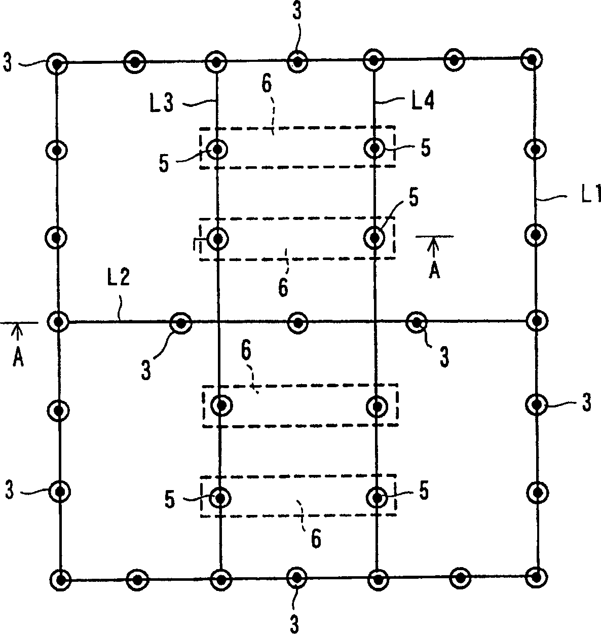
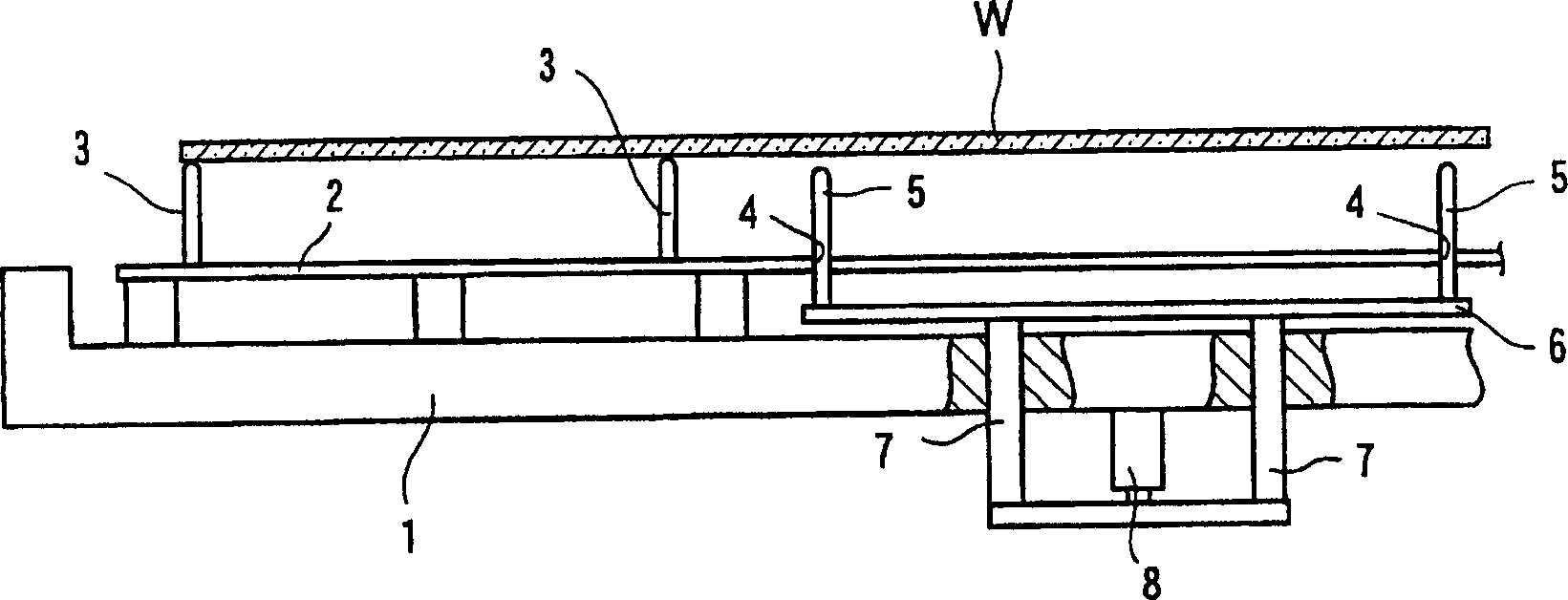
[0033] Embodiments of the present invention will be described below with reference to the drawings. figure 1 It is a top view of the substrate carrying platform of the present invention. figure 2 is along figure 1 An enlarged cross-sectional view of the main part of the line A-A.

[0034] This substrate stage is used, for example, in a process of drying a resist liquid or the like applied on a large glass substrate under reduced pressure.

[0035] The substrate supporting platform is a relatively thin substrate supporting platform installed on the base 1 , and a plurality of fixing pins 3 are installed on the supporting plate 2 . The fixed pin 3 is arranged at a position overlapping the outer peripheral edge L1 outside the effective area of ​​the large substrate W placed on the substrate stage in a plan view, and is also arranged at a position where the large substrate W is cut into two parts. At the position where the scheduled cutting line L2 overlaps.

[0036] On the o...


PUM


Abstract

PROBLEM TO BE SOLVED: To provide a substrate placing stage wherein pins overlap on a cut scheduled line when supporting a large sized substrate where a plurality of substrates are subjected to multiple patterning. SOLUTION: A plurality of fixed pins 3 are mounted on a support plate. The fixed pins 3 are disposed at positions, as viewed in a flat plane, which overlap on an outer peripheral edge L1 located outside the effective area of the large-sized substrate placed on the substrate placing stage, and are also disposed at positions which overlap on a cut scheduled line L2 where the large-sized substrate is subjected to two-face patterning. In contrast, a movable pin 5 is inserted into a through hole formed in the support plate, and the movable pins 5 are disposed at positions which overlap on cut scheduled lines L3, L4 where the large-sized substrate is further subjected to patterning. The lateral movable pins 5 are mounted in common on a coupled plate located below the support plate, hereby elevates the lateral movable pins 5 simultaneously by driving a cylinder unit. COPYRIGHT: (C)2006,JPO&NCIPI

Description

technical field [0001] The present invention relates to a substrate mounting table for carrying a glass substrate when performing various processes on a glass substrate used for a liquid crystal display panel. Background technique [0002] In order to perform various processes with the glass substrate set in a horizontal state, a substrate stage has been used so far. (Patent Documents 1-3) [0003] In the existing substrate carrying platform, a plurality of through holes are formed in the thickness direction of the table surface. Support pins are inserted into these through holes, and a pressure cylinder assembly is used to raise the plurality of support pins at the same time to support the substrate. The support pins are lowered to place the substrate on the table. [0004] Patent Document 1 Japanese Patent Application Laid-Open No. Hei 6-97269 [0005] Patent Document 2 Japanese Patent Application Laid-Open No. Hei 11-111600 [0006] Patent Document 3 Japanese Patent A...

Claims


Application Information

Patent Timeline
Patent Type & Authority Applications(China)
IPC IPC(8): H01L21/687G02F1/13G03F7/26
CPCB65G49/062H01L21/68742H01L21/6875
Inventor 楫间淳生高濑真治山口和伸山本夕记
Owner 艾美柯技术株式会社
Why Eureka
Try Eureka