

Object identification medium and identification method
一种目标物体、识别介质的技术,应用在目标物体的识别介质及识别领域,能够解决通用性低等问题
- Summary
- Abstract
- Description
- Claims
- Application Information
AI Technical Summary
Problems solved by technology
Method used
Image

Examples
Embodiment 1
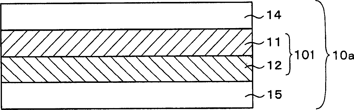
[0085] figure 2 The cross section of the identification medium 10a of Example 1 is shown in . The following descriptions are all common, but since they are stacked upside down during manufacture, the upside-down representation is reversed from the figure.
[0086]First, on the protective film layer 14, a right-handed circularly polarizing polymer cholesteric liquid crystal layer 11 with a helical pitch having a central wavelength of reflected light of 0.70 μm (red) is coated, and a reflective liquid crystal layer 11 is coated thereon. A left-handed circularly polarizing polymer cholesteric liquid crystal layer 12 with a helical structure with a central wavelength of light of 0.55 μm (green) constitutes the first two-layer body 101, and an acrylic adhesive layer 15a is coated thereon. . In the continuation of the process, when the identification medium 10 a produced in this way is immediately attached to the target object 30 , the release paper is not required. In contrast,...
Embodiment 2
[0090] Figure 7 The cross section of the identification medium 10b of the second embodiment is shown in . First, on the protective film layer 14, a right-handed circularly polarizing polymer cholesteric liquid crystal layer 11a having a helical pitch with a center wavelength of reflected light of 0.70 μm (red) is applied, and the The adhesive layer attaches the 1 / 2 wave plate layer 13. The 1 / 2 wave plate layer 13 is composed of polyethylene terephthalate (PET) and adjusted by optical anisotropy so as to shift 1 / 2 wavelength phase. Furthermore, a right-handed circularly polarizing polymer cholesteric liquid crystal layer 11b having a pitch of a helical structure with a center wavelength of reflected light of 0.55 μm (green) is coated thereon to form a second two-layer body 102, and coated thereon. The acrylic adhesive layer 15 is rolled into a roll after laminating the release paper 18 .
[0091] Figure 8 A schematic diagram of a cross-section in which the identification ...
Embodiment 3
[0093] On the 1 / 2 wavelength plate layer 13 made of PET, apply a right-handed circularly polarizing polymer cholesteric liquid crystal layer 11a, emboss the hologram forming layer 19a of the pattern A, and apply an adhesive material 15a thereon. , stick release paper 18 on it, make as Figure 9 Volume A41 as shown in its section.
[0094] Next, the right-handed circularly polarizing polymer cholesteric liquid crystal layer 11b is coated on the protective film layer 14 made of isotropic triacetin cellulose (TAC), and the hologram forming layer 19b of the pattern B is embossed. Processing, coating hot-melt adhesive material 15b on it, make as Figure 10 Volume B42 as shown in its section.
[0095] And, while applying heat and pressure, the roll B42 is bonded to the roll A41 to form a Figure 11 The identification medium 10c shown in. The identification medium 10c includes a second second layer body 102 sandwiching a 1 / 2 wave plate layer 13 between the first and second right-...
PUM
 Abstract
Description
Claims
Application Information