Method for displacably guiding a displaceable machine element of a numerically controlled tool machine or production machine

A technology for moving machines and machine parts, applied in the field of motion guidance, can solve problems such as long processing time and lack of optimal utilization of dynamic performance, and achieve the effect of short processing time

Active Publication Date: 2006-06-21
SIEMENS AG
View PDF0 Cites 5 Cited by
  • Summary
  • Abstract
  • Description
  • Claims
  • Application Information

AI Technical Summary

Problems solved by technology

As a result, the best possible dynamics are not used and the resulting machining times are longer than necessary

Method used


Image

  • Method for displacably guiding a displaceable machine element of a numerically controlled tool machine or production machine
  • Method for displacably guiding a displaceable machine element of a numerically controlled tool machine or production machine
  • Method for displacably guiding a displaceable machine element of a numerically controlled tool machine or production machine

Examples


Embodiment Construction

[0064] The method of the present invention is shown in the form of a structural block diagram in FIG. 4. First, the support point is defined in the function block 28.

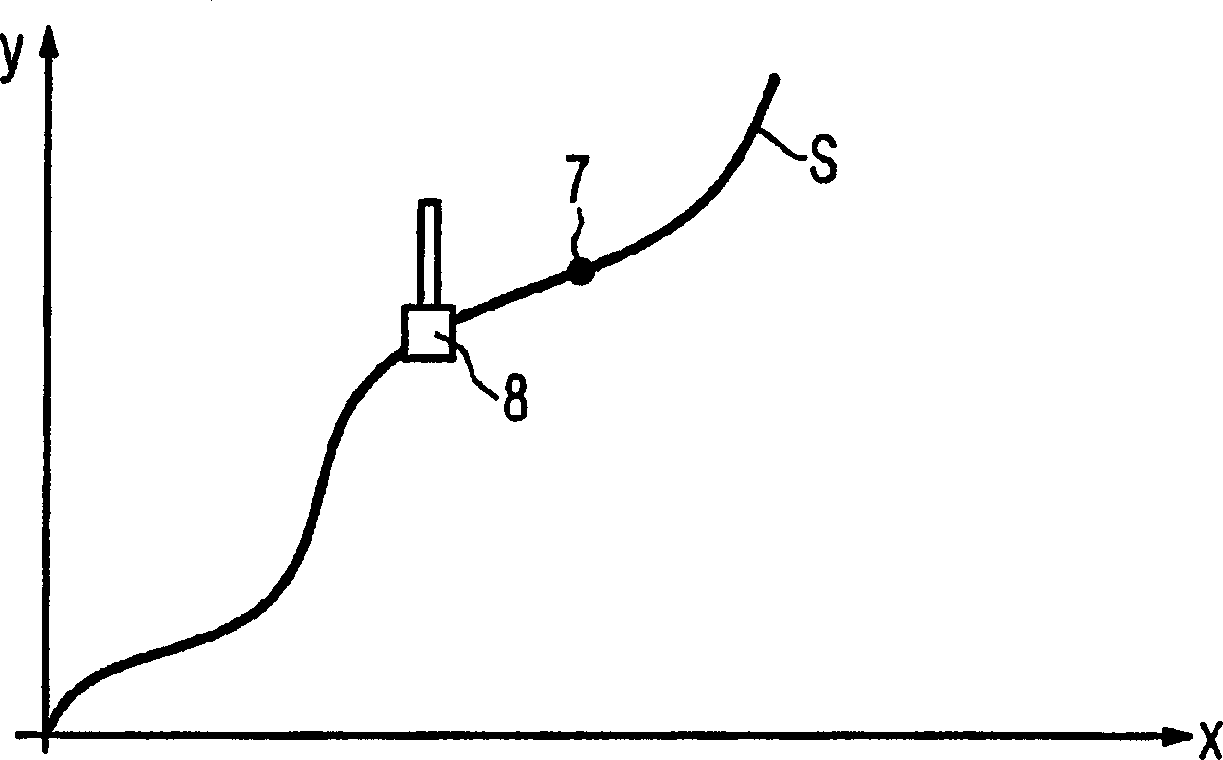
[0065] This is generally based on Figure 6 , Use the spatial lattice to divide the working space 31 of the machine tool, and carry out the movement process of the machine parts in the machine tool. Figure 6 Shows a linear distribution. Of course, it can also be any other lattice form and distribution. Especially in positions that are important for motion guidance, it is meaningful to match the density of the support points around the motion track S. The support points are at the nodes of the dot matrix line segment, for clarity only Figure 6 A support point 32 is shown in. Here, a spatial lattice that becomes a planar lattice is used in the two-axis machine tool used in the embodiment (only a two-dimensional motion track S).

[0066] Then, in the function block 21, the machine part 8 is used to activate the firs...


PUM


Abstract

The invention relates to a method for guiding the motion of a movable machine part (8) of a numerically controlled or special machine tool on a predetermined trajectory (S) of the machine part (8), wherein the workspace (31) of the machine tool is defined The support points (32) within, wherein the maximum possible orbital impulse () and/or the maximum possible orbital acceleration () and/or the maximum possible orbital velocity (), and the movement of the machine part (8) on the moving orbital (S) at the maximum possible orbital impulse () and/or maximum possible orbital acceleration () and/or maximum possible orbital velocity ( )conduct. Thus, the method provides a simple and inexpensive method of optimal motion guidance of a movable machine part (8) of the numerically controlled machine tool on a predetermined trajectory (S) of motion of the machine part (8).

Description

Technical field [0001] The invention relates to a method for guiding a movable machine part of a numerical control machine tool or a special machine tool on a predetermined movement track of the machine part. Background technique [0002] figure 1 The electric drive system commonly used in machine tools is shown in the form of a structural block diagram. in figure 1 In the two-axis machine tool exemplarily shown in, the control device 1 controls the two drive shafts 6a and 6b of the machine tool. The transmission shaft 6a is composed of a regulator 2a, a converter 3a, a transmission motor 4a, and a mechanism 5a connected to the transmission motor 4a. The transmission shaft 6b is composed of a regulator 2b, a converter 3b, a transmission motor 4b, and a mechanism 5b connected to the transmission motor 4b. The control device 1 respectively predetermines the position setpoints of the adjuster 2a and the adjuster 2b of each transmission shaft according to the predetermined movemen...

Claims


Application Information

Patent Timeline
Patent Type & Authority Applications(China)
IPC IPC(8): G05B19/41B25J9/16
CPCG05B19/41G05B2219/43062G05B2219/49295
Inventor 克劳斯·盖斯多尔弗卡斯滕·哈姆沃尔夫冈·帕皮尔尼克
Owner SIEMENS AG
Why Eureka
Try Eureka