Signal receiver for position finding

一种信号接收装置、测位的技术,应用在测量装置、产生/分配信号、无线电波测量系统等方向,能够解决电源消耗降低效果小、装置消耗电流变大等问题

一种信号接收装置、测位的技术,应用在测量装置、产生/分配信号、无线电波测量系统等方向,能够解决电源消耗降低效果小、装置消耗电流变大等问题

CN1794008AInactive Publication Date: 2006-06-28FURUNO ELECTRIC CO LTD

Image

  • Signal receiver for position finding
  • Signal receiver for position finding
  • Signal receiver for position finding

Examples


Embodiment Construction

[0034] An example of a GPS receiving device according to an embodiment of the present invention will be described with reference to FIGS. 1 to 9 .

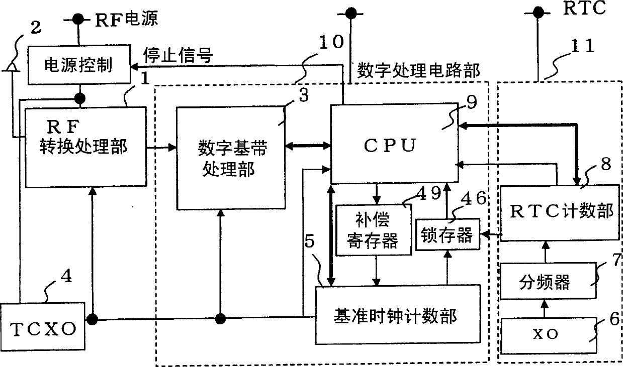
[0035] FIG. 2 is a block diagram showing the configuration of a GPS receiver.

[0036] The RF conversion processing unit 1 converts the signal received by the antenna 2 into an intermediate frequency signal and at the same time converts it into a digital signal. The digital baseband signal processing unit 3 processes the digital signal to generate information for detecting the C / A code phase and the carrier phase. In addition, a temperature-compensated crystal oscillator (TCXO) 4 of the reference clock signal generation circuit generates a reference clock signal of 16.3678 MHz. The reference clock counting unit 5 counts the reference clock.

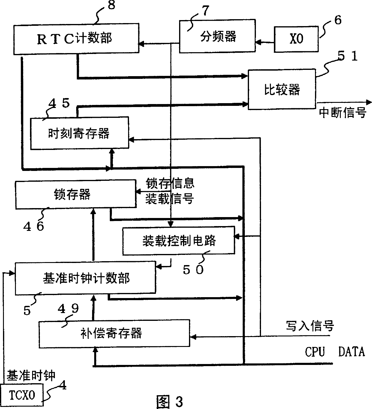
[0037]On the other hand, a crystal oscillator (XO) 6 , which is a part of the low-frequency clock signal generation circuit, oscillates at a low frequency of 32.768 KHz. The frequency divi...


PUM


Abstract

Provided is a signal receiving device for position measurement, which includes: an intermittent action control mechanism, which keeps the RTC unit (11) in constant action, directly changes the action of the TCXO (4) to a stop state only within a specified stop time, and After the stop time expires, the intermittent operation of returning from the above stop state is repeated; the count ratio determining mechanism calculates the number of counts of the clock signal of the TCXO (4) and the RTC unit (11) within a predetermined time before the above stop time The count ratio of the number of counts of the clock signal; the reference clock count value insertion mechanism, which calculates the clock signal of the TCXO within the above-mentioned stop time from the above-mentioned count ratio and the count number of the RTC part (11) within the above-mentioned stop time and insert the clock of the TCXO at the end of the above stop time with the above number of analog counts. Intermittent operation is performed with less power consumption than before, and positioning can be quickly performed after recovery from a stop state.

Description

technical field [0001] The present invention relates to a signal receiving device for position measurement which receives a plurality of signals for position measurement and measures the position of a receiving point. Background technique [0002] In a positioning signal receiving device such as a conventional GPS receiving device, radio waves transmitted from a plurality of positioning satellites are received, and the GPS time and, The position of each positioning satellite, the simulated distance between each positioning satellite and the receiving point, and the positioning system time are also obtained from the position of each positioning satellite and the simulated distance to the receiving point. [0003] In the above-mentioned GPS receiving device, although the position measurement is usually continued directly after the power is turned on in use, for example, a portable positioning device using a small-capacity battery as a power source, or a solar cell and a second...

Claims


Application Information

Patent Timeline
28 Jun 2006
Publication
CN1794008A
IPC
G01S19/23; G01S19/34; H04B1/16
CPC
G01S19/23; G01S19/34; G06F1/04; G06F1/3203; G06F1/324; Y02D10/00; Y02D30/50
Inventors
安本卓司