Method for fabricating direction matched magnet in profiled square inner diameter of annular ferrite magnetic pole, and structure

A ferrite magnet and manufacturing method technology, applied in the manufacture of permanent magnets, inductors/transformers/magnets, magnetic circuits, etc., can solve the problems of insufficient magnetic force, easy breakage, good magnetic properties, etc., to improve the surface magnetic flux density, Strong acid and alkali resistance and moisture resistance, and the effect of improving the magnetic field strength

Inactive Publication Date: 2006-07-05
SUPER ELECTRONICS
View PDF0 Cites 10 Cited by
  • Summary
  • Abstract
  • Description
  • Claims
  • Application Information

AI Technical Summary

Problems solved by technology

[0014] 1. When assembled, an air gap is formed between the magnets and the magnetic flux is easy to leak, so that there will be cogging when the annular permanent magnet 8 is running
[0015] 2. Since the ring-shaped permanent magnet 8 is composed of several half-moon disks, it takes a lot of work to assemble and process, and the inner roundness is poor
[0017] 4. The sintering temperature of the ferrite magnet is about 1240°C. The thickness of the magnet should not be too thin during sintering, otherwise it will be easily broken. Therefore, the outer diameter of the ring-shaped magnet will be larger when assembled, and the aluminum shell of the overall hub will be bulky.
[0018] 5. Due to the above-mentioned problems such as magnetic flux leakage, cogging torque, insufficient magnetic force, and large outer diameter, the ring-shaped permanent magnet formed by using this half-moon-shaped anisotropic ferrite magnet has not been certified by the standard yet. ; Relatively uncompetitive in terms of added value of goods
If a ring die is used for stamping and the traditional alignment method is applied, the alignment position of the stamped ring blank body will not match the position of the required working surface, and it cannot be used even after magnetization. The main reason why it was not possible to integrally form ferrite magnets with many advantages into a ring shape
[0022] Furthermore, as mentioned earlier, in terms of magnetic properties alone, the materials of ferrite magnets are not as good as those of NdFeB series materials.

Method used


Image

  • Method for fabricating direction matched magnet in profiled square inner diameter of annular ferrite magnetic pole, and structure
  • Method for fabricating direction matched magnet in profiled square inner diameter of annular ferrite magnetic pole, and structure
  • Method for fabricating direction matched magnet in profiled square inner diameter of annular ferrite magnetic pole, and structure

Examples


Embodiment Construction

[0053] The technical features and achieved effects of the present invention will be described in detail below with reference to the embodiments and accompanying drawings, so that readers can have a deeper understanding of the present invention.

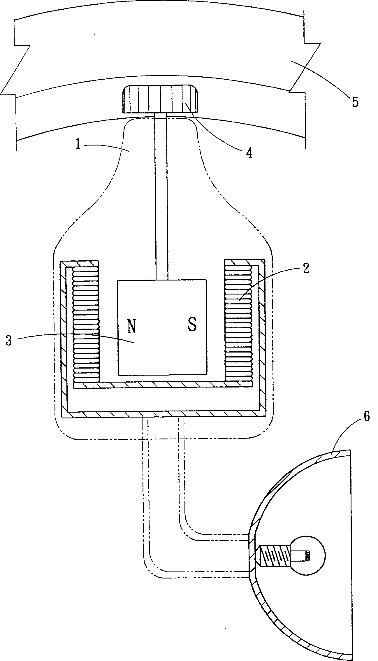
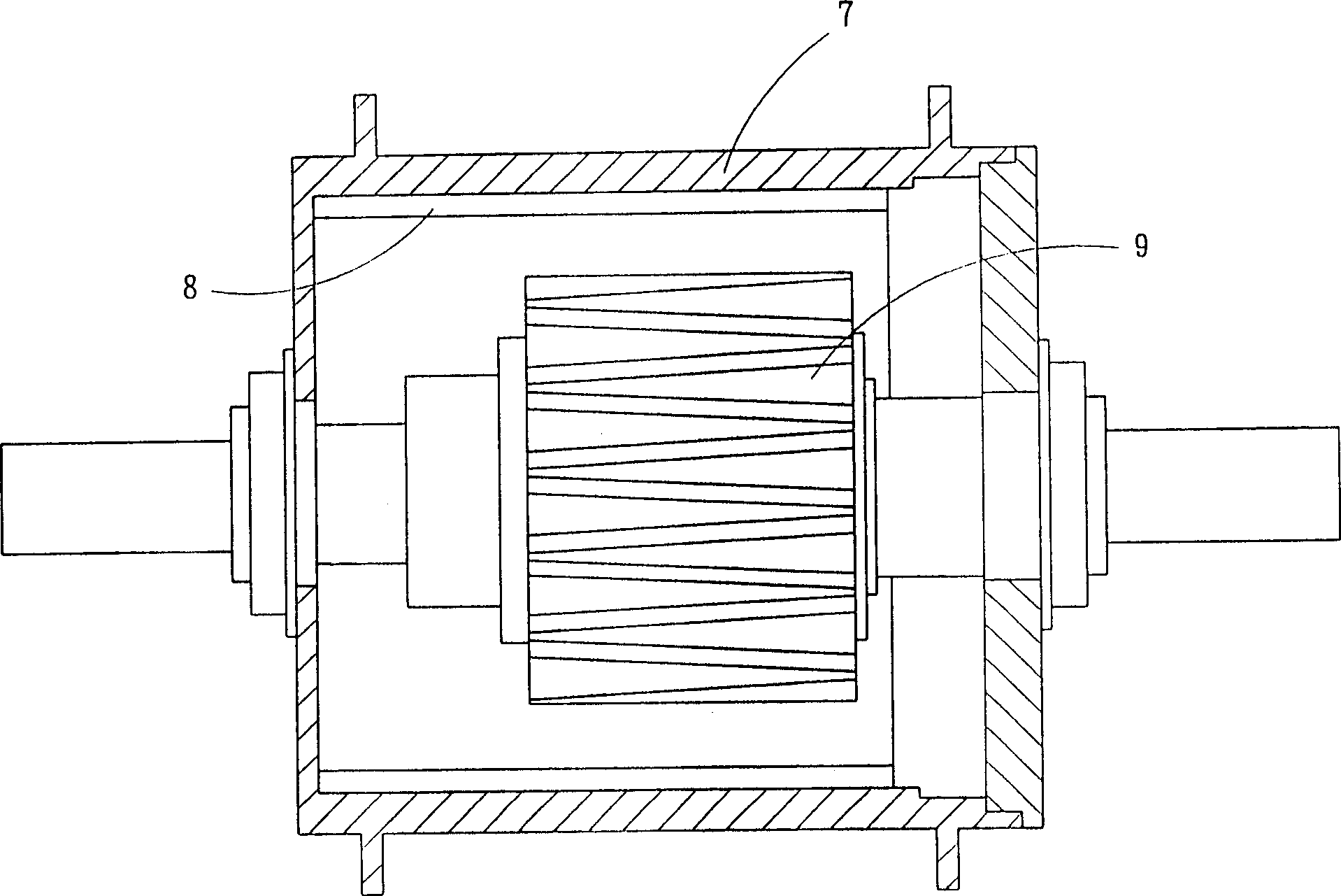
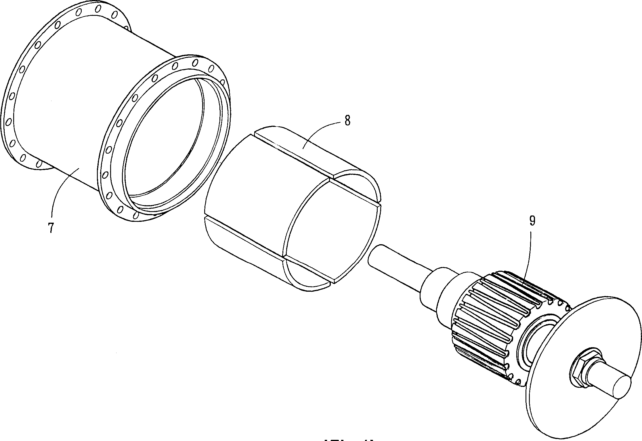
[0054] Such as Figure 4-Figure 6 As shown, the manufacturing method of the ring-shaped ferrite magnet of the present invention with different inner diameter alignment magnets is aimed at brushless DC motors and bicycle hub-type generators (Hub-Dynamo) or other outer-rotating generators. The permanent magnets used in the outer rotor provide an innovative manufacturing method and improved structure of the ring-shaped ferrite magnets with different square inner diameter alignment magnets. The processes include: powder process, granulation, stamping and alignment, sintering, Grinding and magnetization detection steps are characterized in that:

[0055] After the granulated magnetic powder 50 is filled into the mold set having an annular...


PUM


Abstract

The invention discloses technique and structure of permanent magnet in use for DC brushless outer rotating type motor and outer rotor of hub-dynamo in bicycle. Reasonable price makes product possible to be applied to varied bicycles and DC brushless outer rotating type rotor. Advantages are: reduced magnetic leakage, increased density of magnetic beam on surface, and magnetic field strength besides acid and alkali proof, high moisture resistance of material.

Description

technical field [0001] The present invention relates to a manufacturing method and structure of a ring-shaped ferrite magnet with different square inner diameter alignment magnets, which is mainly applied to permanent magnets used in external rotation generators, especially suitable for bicycle hub-type generators (Hub-Dynamo), Or other externally rotating generators and DC brushless externally rotating motors. Background technique [0002] Bicycles are widely used for leisure and transportation, and even in today's automobile heyday, bicycles are still widely loved by the world. Because it is easy to disassemble, assemble and repair, which is unmatched by any other means of transportation. In particular, the generator and lighting components (commonly known as motorized lamps) in bicycle parts are ingeniously combined with manpower and mechanism design, which can not only replace consumable energy such as oil, but also take into account the maintenance of the environment a...

Claims


Application Information

Patent Timeline
Patent Type & Authority Applications(China)
IPC IPC(8): H01F41/02H01F1/10H01F7/02H02K1/00
CPCH01F1/08H01F41/028
Inventor 陈己文
Owner SUPER ELECTRONICS
Why Eureka
Try Eureka