Method for mounting compressor piston and slipper into cylinder

A cylinder block and compressor technology, applied in the field of compressor manufacturing, can solve the problems of piston falling off, high labor intensity, time-consuming and labor-intensive problems

Inactive Publication Date: 2006-07-12
SANDEN HUAYU AUTOMOTIVE AIR CONDITIONING CO LTD
View PDF0 Cites 2 Cited by
  • Summary
  • Abstract
  • Description
  • Claims
  • Application Information

AI Technical Summary

Problems solved by technology

[0005] 1. When installing the piston 4 and the sliding shoe 3 on the swash plate of the main shaft swash plate part 2, it is quite difficult to fully assemble the multiple pistons 4 and sliding shoes 3 because there is no outer ring to stop it, and it is easy to cause the assembled Piston and sliding shoes fall off
[0006] 2. The fit gap between the piston 4, the sliding shoe 3 and the swash plate is quite small, and it takes time and effort to...

Method used


Image

  • Method for mounting compressor piston and slipper into cylinder
  • Method for mounting compressor piston and slipper into cylinder
  • Method for mounting compressor piston and slipper into cylinder

Examples


Embodiment Construction

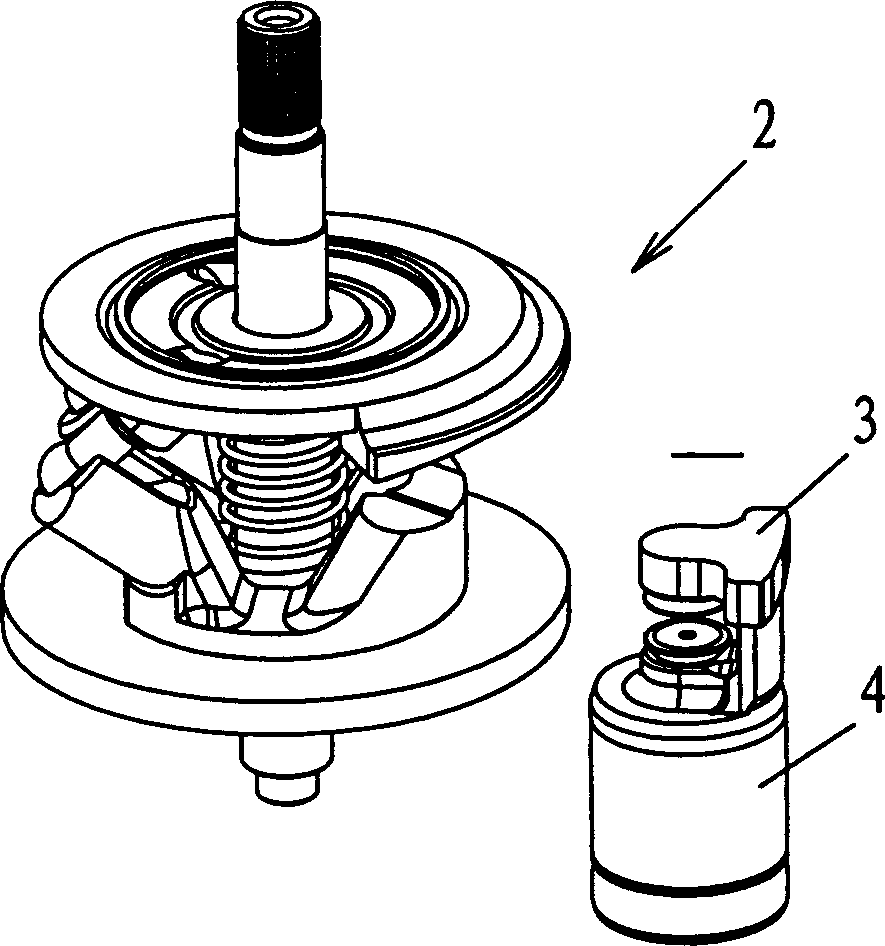
[0023] The present invention utilizes the characteristic that the swash plate of the variable displacement compressor has a variable angle, and the piston and the sliding shoe are loaded into the cylinder body at one time by inclining the swash plate at a certain angle.

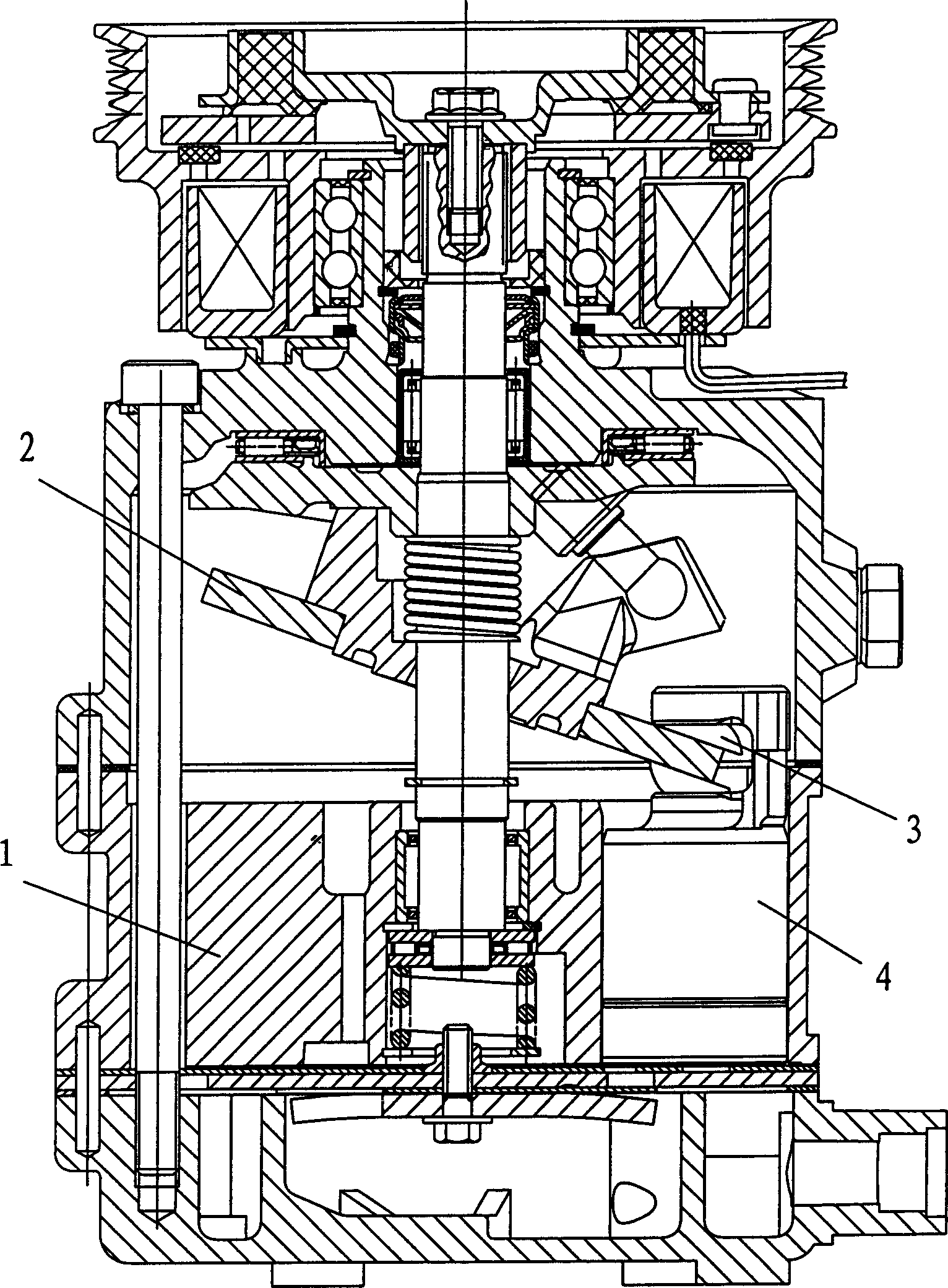
[0024] like Figure 7 As shown, the cylinder block 1 is first placed on a rotatable turntable 21, and the main shaft swash plate component 1 is lifted to a certain position directly above its installation position through a lifting and supporting mechanism (not shown in the figure). , so that a certain space is reserved between the swash plate 20 and the cylinder block 1, and the swash plate 20 is in a nearly horizontal position due to the elastic force of the spring.

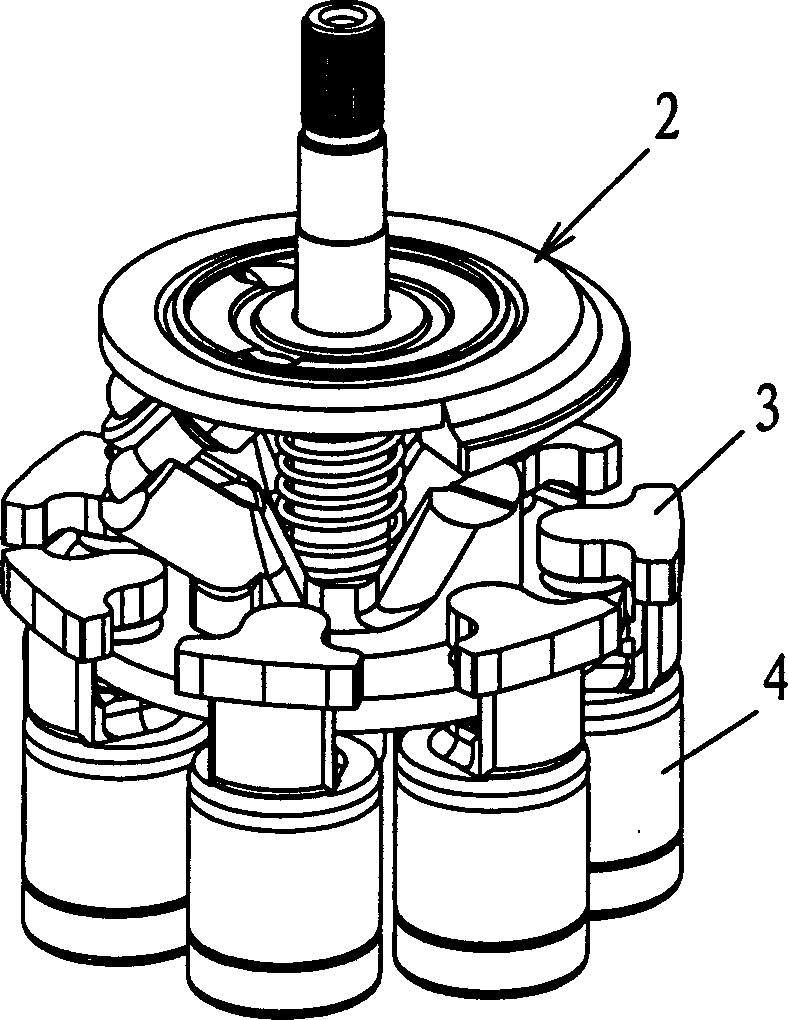
[0025] like Figure 8 As shown, then turn the swash plate 20 to a certain angle along the deflection direction of the swash plate. At this time, the maximum space generated by the lifting of the cylinder block and the deflection of the swash ...


PUM


Abstract

The invention relates to a method for putting the compressor piston and slipper into cylinder, while the traditional method has hard installment and easy abrasion of piston. The inventive method comprises: (1) putting the cylinder on a rotational disc; (2) putting the main axle inclined disc element above the cylinder with a distance between them; (3) rotating the inclined disc of main axle inclined disc element to make the maximum space between the cylinder and the inclined disc be able to contain mounted piston and rotating the cylinder disc to make one piston hole of it aim said maximum space; (4) mounting the piston and slipper on the highest point of inclined disc and loosening the inclined disc to make it recover to horizontal position, and the piston enters relative piston hole; (5) repeating the steps from (2)-(4), putting each piston into relative piston hole; (6) descending the main axle inclined disc element and the piston to be packed in the cylinder. The invention can reduce the mounting hardness and time with improved mounting quality.

Description

technical field [0001] This invention relates to the manufacture of compressors and, in particular, to the method of incorporating compressor pistons and shoes into cylinder blocks. Background technique [0002] The structure of the variable displacement compressor is as follows: figure 1 As shown, the core components in its body components include cylinder block 1, main shaft swash plate component 2, sliding shoe 3 and piston 4. Piston 4 is installed in the piston hole of cylinder block 1, and is connected on a swash plate that can change the angle within a certain range through sliding shoe 3. The drive plate fixed on the main shaft 1 (drive shaft) drives the swash plate to rotate, so that the piston 4 makes a reciprocating linear motion in the piston hole rhythmically to realize the suction and exhaust process of the compressor. [0003] In order to make the compressor have a smaller volume and weight while obtaining a maximum displacement, the assembly structure betwee...

Claims


Application Information

Patent Timeline
IPC IPC(8): F04B39/14F04B27/10
Inventor 王榕屠安民王陈巍
Owner SANDEN HUAYU AUTOMOTIVE AIR CONDITIONING CO LTD
Why Eureka
Try Eureka