Variable valve lift control system for a combustion engine with underneath camshaft

A valve lift, internal combustion engine technology, applied in the direction of valve devices, mechanical equipment, engine components, etc., can solve problems such as comfort damage, and achieve cost-effective results

Inactive Publication Date: 2006-07-12
HYDRAULIK RING +1
View PDF4 Cites 30 Cited by
  • Summary
  • Abstract
  • Description
  • Claims
  • Application Information

AI Technical Summary

Problems solved by technology

Thus, at this load point, the valve lifts between the cylinders may only differ by a value of approximately 10%, because otherwise the entire engine would

Method used


Image

  • Variable valve lift control system for a combustion engine with underneath camshaft
  • Variable valve lift control system for a combustion engine with underneath camshaft
  • Variable valve lift control system for a combustion engine with underneath camshaft

Examples


Embodiment Construction

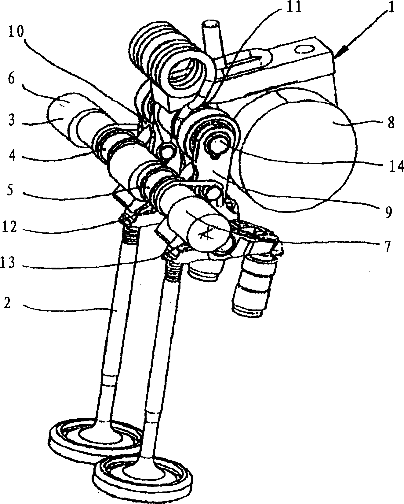
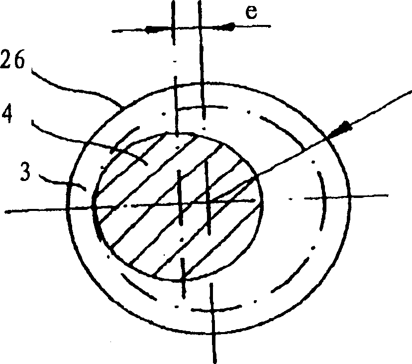
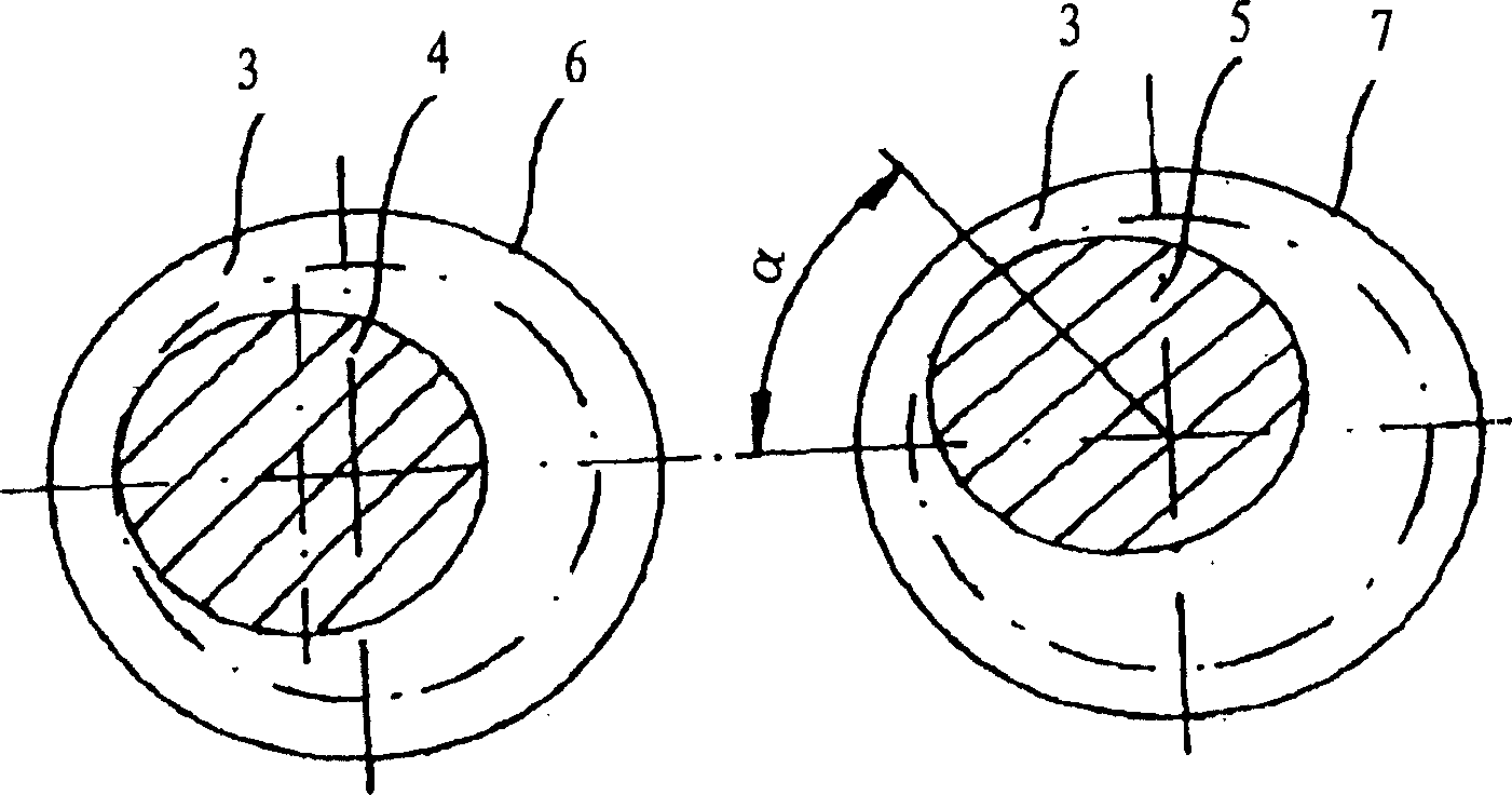
[0119] figure 1 shows a valve lift system for variable lift adjustment of the gas exchange valve 2 of a valve lift device 1 presenting a rotatable eccentric shaft 3 comprising several eccentrics 4, 5, where all possible contours of the eccentrics 4, 5 lie within a circle formed by means of the outer diameters of the bearings 6, 7 of the eccentric shaft 3 ( figure 2 ). The eccentric shaft 3 can be inserted through a through-bore in the material of the cylinder head (not shown) and engages directly in the through-bore in the cylinder head. Thereby, the eccentric shaft 3 can be mounted as an insertable eccentric shaft 3 from one of the front walls of the cylinder head. The eccentric shaft 3 can be embedded in a separate housing, which is connected to the cylinder head. In the housing, the eccentric shaft 3, the rocker levers 9, 10, the camshaft 8 and the slotted connecting rod 11 are inserted as pre-assembled units. It is also possible to engage the eccentric shaft 3 by mean...


PUM


Abstract

In order to produce a variable valve lift device for the lift adjustment of the gas-exchange valves of an internal combustion engine, by means of which with adjustment forces and holding forces, independently from whether said holding forces and adjustment forces are applied mechanically, hydraulically or electrically, with an adjustment of the valve lift being as cost-effective as possible, and with maximum accuracy of the adjustment or control of the valve lift to be taken between the individual cylinders of a multi-cylinder internal combustion engine, and, moreover, the adjustment possibility of the valve lift of the valves of an internal combustion engine with several cylinders is obtained within smallest tolerances, it is suggested that a valve lift device (1) has a rotatable eccentric shaft (3), which consists of several eccentrics (4, 5) and whereby all possible contours of the eccentrics (4, 5) are positioned within a circle, which is formed by means of the external diameters of a bearing (6, 7) of the eccentric shaft (3).

Description

technical field [0001] The invention relates to a variable valve lift device for lift adjustment of a gas exchange valve of an internal combustion engine according to the preamble of patent claim 1 . Background technique [0002] Adjusting devices for lift adjustment of gas exchange valves of internal combustion engines are known from DE19548389A1 and DE10123186A1, whereby the adjusting device in DE19548389A1 has an eccentric shaft for setting or alignment of the valve lift of the gas exchange valves, the The eccentric shaft is rotatably embedded in the cylinder head by means of an electric motor driven by a worm gear by means of the motor shaft, the motor shaft and the worm gear being positively connected via gears with the eccentric shaft and a control unit which controls the electric motor. The setting of an adjustable lift by means of an eccentric is also known from the prior art. The forces necessary for the eccentric torsion and eccentric support in the adjusted valve...

Claims


Application Information

Patent Timeline
IPC IPC(8): F01L13/00F01L1/344F01L1/46F01L1/18F01L1/14F01L1/24F01L1/053F01L1/34
CPCF01L1/2405F01L13/0021F01L1/34F01L1/146F01L1/24F01L13/0005F01L2013/0068F01L2101/00F01L1/18F01L13/0026F01L13/0063F01L1/2422F01L2105/00F01L2301/00F01L2305/00F01L13/00F01L1/14
Inventor 格林德·博斯尔-弗利尔鲁道夫·弗利尔威廉·汉尼巴尔米夏埃尔·尤贝尔特安德列亚斯·克内希特安德列亚斯·维尔德
Owner HYDRAULIK RING
Why Eureka
Try Eureka