Vertical grinder

A vertical mill and grinding disc technology, applied in grain processing and other directions, can solve the problems of high manufacturing difficulty, high cost and complex structure, and achieve the effects of simple structure, reliable operation and low cost.

Inactive Publication Date: 2006-07-19
夏纪勇
View PDF0 Cites 16 Cited by
  • Summary
  • Abstract
  • Description
  • Claims
  • Application Information

AI Technical Summary

Problems solved by technology

Therefore, the performance requirements of the vertical mill reducer are high, the structure is complex, the manuf

Method used


Image

  • Vertical grinder

Examples


Embodiment Construction

[0011] The present invention will be further described below in conjunction with the drawings.

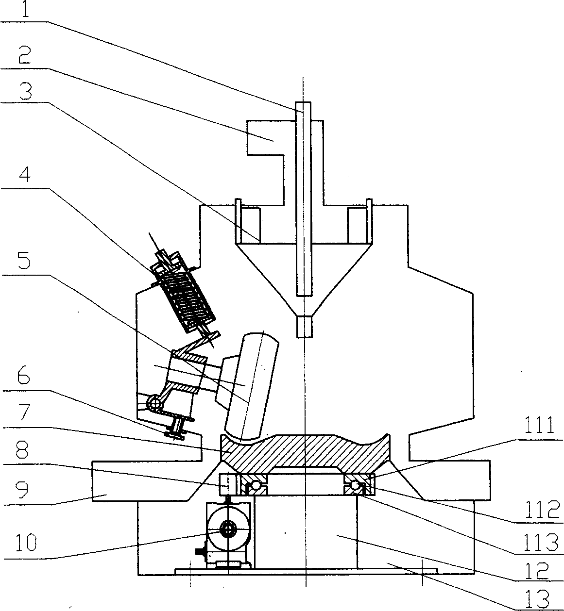
[0012] This embodiment is a vertical mill in which the upper feed is used, the materials are discharged from the upper part by wind classification, and the spring mechanism is used as the pressure device.

[0013] As shown in the figure, this embodiment consists of the feed port 1, the discharge port 2, the grading cone 3, the pressure device 4, the grinding roller 5, the adjusting screw 6, the grinding disc 7, the transmission wheel 8, the air inlet 9, and the reduction device 10. Rotary ring 111, rolling element 112, stationary ring 113, bearing support 12, machine seat 13, etc.; the material to be ground enters the machine from the feed port 1 and falls onto the grinding disc 7, and the pressure device 4 faces the grinding roller 5. The grinding force is applied, and the adjusting screw 6 is used to adjust the gap between the grinding roller 5 and the grinding disc 7. The slewing be...


PUM


Abstract

The invention discloses a vertical mill, which comprises the following parts: feed inlet, discharge port, grinding roll, grinding disk, pressuring device, grinding roll, grinding disc gap adjusting device, rotary bearing, bearing support, deceleration device and stand, wherein the stand is fixed on the ground; the bearing support is set on the stand or ground directly; the grinding disk is set on the bearing support through rotary bearing; the output end of deceleration device connects the rotary coil of rotary bearing through flange, gear or other driving part, which can be gear deceleration device and belt deceleration device or the combination with two devices on the bearing support, stand or ground directly.

Description

Technical field [0001] The invention relates to a vertical mill, in particular to a vertical mill used for grinding various materials in industries such as metal mines, non-metal mines, energy sources, and new materials. Background technique [0002] The vertical mill commonly used in industry is a kind of roller mill. Its basic principle is to place the material to be ground between the grinding roller and the grinding disc, and use mechanical force such as spring force and hydraulic pressure or centrifugal force generated by rotation. It is crushed and crushed. This kind of grinding equipment using the principle of material bed extrusion and crushing has the characteristics of higher grinding efficiency, lower power consumption and less wear than the grinding equipment using shear and impact force. There are many types of vertical mills. Here, a widely used MPS vertical mill with a rotating disc and a relatively stationary roller (not revolving around...

Claims


Application Information

Patent Timeline
IPC IPC(8): B02C15/00B02C23/08
Inventor 夏纪勇
Owner 夏纪勇
Why Eureka
Try Eureka