
Method for precisely measuring incident angle by means of laser feedback and application thereof

A laser feedback and incident angle technology, applied in the field of optical detection, can solve the problems of increased instrument cost and low precision, and achieve the effects of reduced production and use costs, high precision, and good market prospects

Inactive Publication Date: 2006-07-19
SOUTH CHINA NORMAL UNIVERSITY +1
View PDF0 Cites 6 Cited by
  • Summary
  • Abstract
  • Description
  • Claims
  • Application Information

AI Technical Summary

Problems solved by technology

At present, in the prism coupling test systems built by various laboratories, the determination of the 0° reference angle is carried out by observing whether the light spot of the beam reflected by the prism surface enters the light source exit barrier with the human eye, which is a simple method. method, but the accuracy is not high; in commercial testers, for example, Metricon in the United States TM Both the 2010 Prism Coupler and the Korean SPA Series Prism Coupler are equipped with an automatic calibration system dedicated to determining the 0° reference angle, which significantly increases the cost of the instrument

Method used


Image

  • Method for precisely measuring incident angle by means of laser feedback and application thereof
  • Method for precisely measuring incident angle by means of laser feedback and application thereof
  • Method for precisely measuring incident angle by means of laser feedback and application thereof

Examples


Embodiment 1

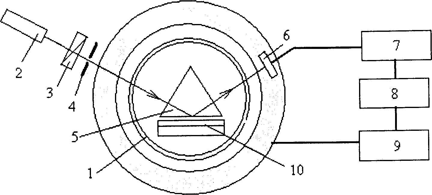
[0015] figure 1 The specific structure of the slab waveguide synchronous angle device using the prism coupling method of the present invention is shown, by figure 1 It can be seen that the device includes components such as a rotating platform 1, a laser 2, a polarizer 3, a diaphragm 4, a prism 5, a detector 6, an A / D converter 7, a computer 8, and a stepping motor 9. Place the slab waveguide 10 (the slab waveguide is composed of a substrate and a film attached to it), the laser light emitted by the laser 2 passes through the polarizer 3 and the diaphragm 4 and enters the prism 5, and is reflected by the prism 5 and then enters the detector 6. The detector 6 is connected with the A / D converter 7 and the computer 8 , and the stepping motor 9 which drives the platform 1 to rotate is connected with the computer 8 at the same time. Utilize aforementioned device to realize the concrete steps of the inventive method and be: the operator sends instruction by computer, allows stepper...

Embodiment 2

[0019] This embodiment is the same as embodiment 1 except the following features: for the same measurement point, keep the same test conditions as in embodiment 1, the prism rotates counterclockwise, and table 2 is the number of steps of the above-mentioned three adjacent guided modes measured displacement, measured three times.

[0020] Table 2

[0021]

[0022] Take the average value of the clockwise and counterclockwise step displacements of the same pattern, and multiply the average step displacement by the step angle value, which is the corresponding incident angle of this point. In this embodiment, through two-way measurement, the measurement error caused by the change of the output light intensity of the light source lagging behind the reflected light entering the light source is eliminated, so the result is more accurate. Table 3 is the average value of step number displacement and the refractive index and film thickness (step length angl...


PUM


Abstract

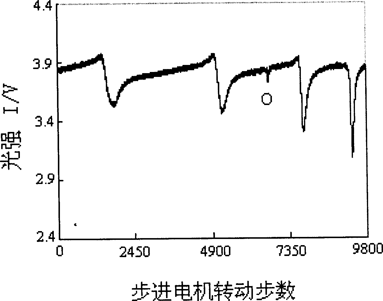
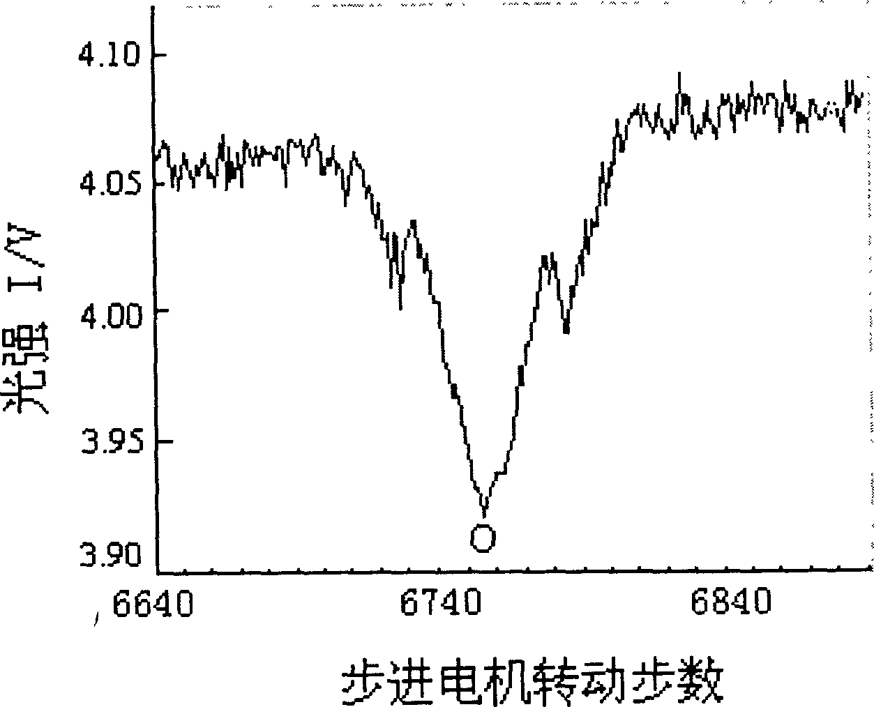
The invention provides a method for using laser feedback to ascertain the enlarged dash with high accurate, which rotates the laser light source or plane interface opposed dash point to enlarged dash 0 deg. location along the enlarged dash reducing direction and keeps the light beam in the same dash surface when rotating it, it measures the reflecting light curve which is changed with the change of the enlarged dash; it spreads out the curve on the drawing software in the range of 0 deg., the laser feedback makes the output light intensity to generate flucticulus, it ascertains the wave bottom point as 0 deg. reference angle; it then uses the displacement of one point relative to 0 deg. reference angle to multiply with the length to obtain the corresponding enlarged dash.

Description

technical field [0001] The invention relates to optical detection technology, in particular to a method for determining the incident angle with high precision by using laser feedback and its application. Background technique [0002] Optical waveguides are important fundamental components in integrated optics. Optical devices based on planar optical waveguide technology have the advantages of low cost, small size, easy mass production, good stability, and easy integration with other devices. At present, integrated optical devices have played an important role in communication, military, electric power, astronomy, sensing and other application fields. The refractive index and film thickness of planar optical waveguides are the basis for designing and manufacturing optical waveguide devices. Therefore, high-precision detection of planar optical waveguide parameters has very important research and application value. At present, the technology that can s...

Claims


Application Information

Patent Timeline
Patent Type & Authority Applications(China)
IPC IPC(8): G01N21/41G01B11/06
Inventor 张小康廖常俊刘颂豪
Owner SOUTH CHINA NORMAL UNIVERSITY
Learn More