Energy-saving plasma display panel driving method and its apparatus
A technology of plasma and driving method, which is applied in the direction of identification devices, static indicators, instruments, etc., can solve the problems of large electromagnetic interference, large reactive power, and low energy recovery efficiency, and achieve reduction of reactive power and electromagnetic interference, The effect of eliminating parasitic effects and improving energy saving efficiency
- Summary
- Abstract
- Description
- Claims
- Application Information
AI Technical Summary
Problems solved by technology
Method used
Image
Examples
Embodiment 1
[0054] Such as Figure 6 , 7 , 10, and 11.
[0055] Figure 6 It is an energy-saving driving device according to Embodiment 1 of the present invention. Including the basic first energy-saving driving circuit and the second energy-saving driving circuit, the light-emitting unit quantity measuring device ( Figure 10 ) controls the timing generator ( Figure 11 ).
[0056] Measuring device for the number of light emitting units ( Figure 10 ) statistics the image data to be displayed in each subfield, and its circuit can be realized by a logic circuit (FPGA can be used to add a logic program), and a specific program is as follows:
[0057] process(dotclk, Vsync, DisplayEN, RGB) begin if Vsync='0'then cntcntcntcntcnt
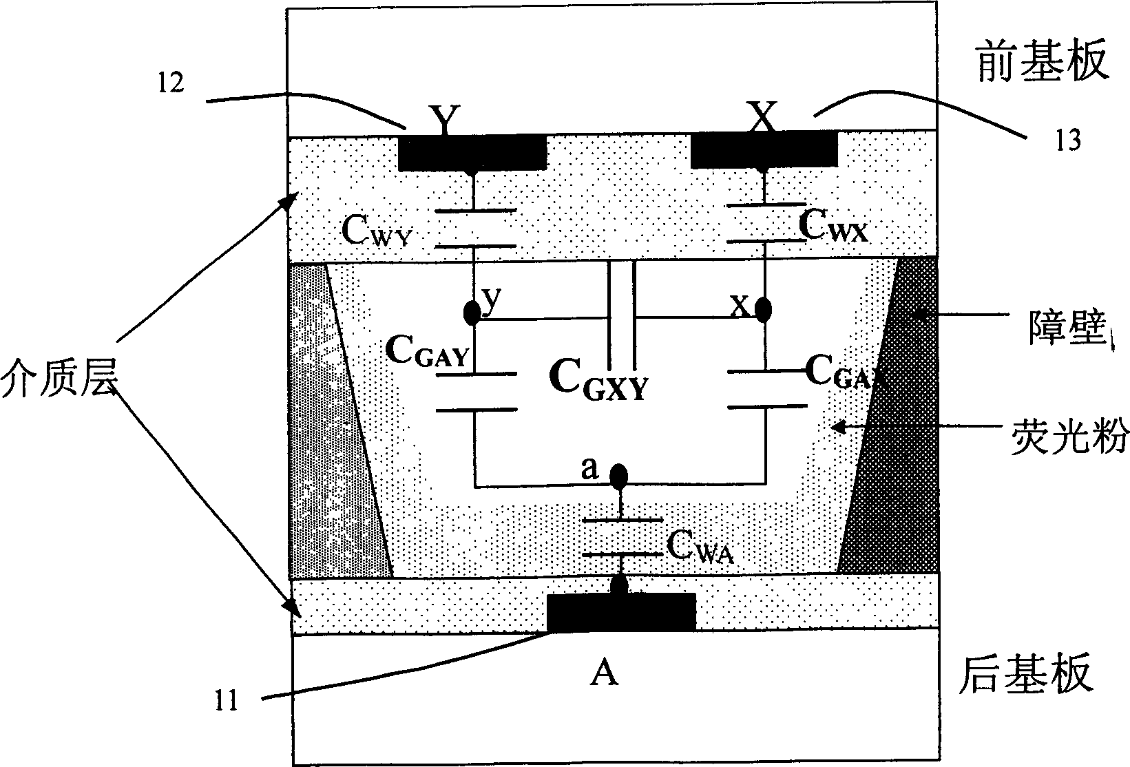
[0058] The count value of the above program directly reflects the load status of the plasma display panel and its parasitic capacitance value, and the result is sent to the control timing generator, which adjusts S11, S12, S13, S14, S21, S22 according to t...
Embodiment 2
[0062] Such as Figure 8 , 9 , 10, and 11.
[0063] Figure 8 It is the energy-saving driving device of the second embodiment of the present invention. It includes a first energy-saving driving circuit and a second energy-saving driving circuit, an image load counting device and a control timing generator. Both the first energy-saving driving circuit and the second energy-saving driving circuit include a basic energy-saving unit composed of n-routing switching elements and a resonant inductor. Here, only the first energy-saving driving circuit is taken as an example for illustration.
[0064] The first energy-saving driving circuit includes n groups of basic energy-saving units. In actual implementation, n can take an appropriate value according to the actual situation. Taking into account cost and performance factors, the value of n is between 2 and 10. The values of inductances L1, L2,...Ln are in multiples, that is, Ln:Ln-1:...L2:L1=2n:2(n-1):... : 2: 1, of course, t...
Embodiment 3
[0067] This implementation example combines the implementation example 1 and the implementation example 2 to realize together. The specific form of the device is the same as that of the second embodiment, and the control sequence combines the characteristics of the first embodiment.
[0068] Specifically, as Figure 8 As shown, the image load counting device counts the image data to be displayed, and sends the result to the control timing generator, which adjusts S11-1 and S12 according to the load status of the plasma display panel and the parasitic capacitance corresponding to the count value -1, S11-2, S12-2, ... S11-n, S12-n and other control signals enable the corresponding energy-saving units to be turned on and off according to the displayed load conditions, that is, the basic energy-saving units participating in the resonance With the change of the equivalent capacitance of the PDP display screen, it participates in energy saving work. At the same time, the relative ...
PUM
 Abstract
Description
Claims
Application Information
 - R&D
- Intellectual Property
- Life Sciences
- Materials
- Tech Scout
- Unparalleled Data Quality
- Higher Quality Content
- 60% Fewer Hallucinations
Browse by: Latest US Patents, China's latest patents, Technical Efficacy Thesaurus, Application Domain, Technology Topic, Popular Technical Reports.
© 2025 PatSnap. All rights reserved.Legal|Privacy policy|Modern Slavery Act Transparency Statement|Sitemap|About US| Contact US: help@patsnap.com


