
Collecting tube with detection hole

A technology of detection holes and test holes, which is applied in the field of spinning device components, can solve problems such as affecting spinning quality, low production efficiency, troublesome operation, etc., so as to avoid inconvenient operation, improve spinning quality and production efficiency, and simplify operation Effect

Inactive Publication Date: 2006-07-26
NINGBO DECHANG PRECISION TEXTILE MACHINERY
View PDF0 Cites 3 Cited by
  • Summary
  • Abstract
  • Description
  • Claims
  • Application Information

AI Technical Summary

Problems solved by technology

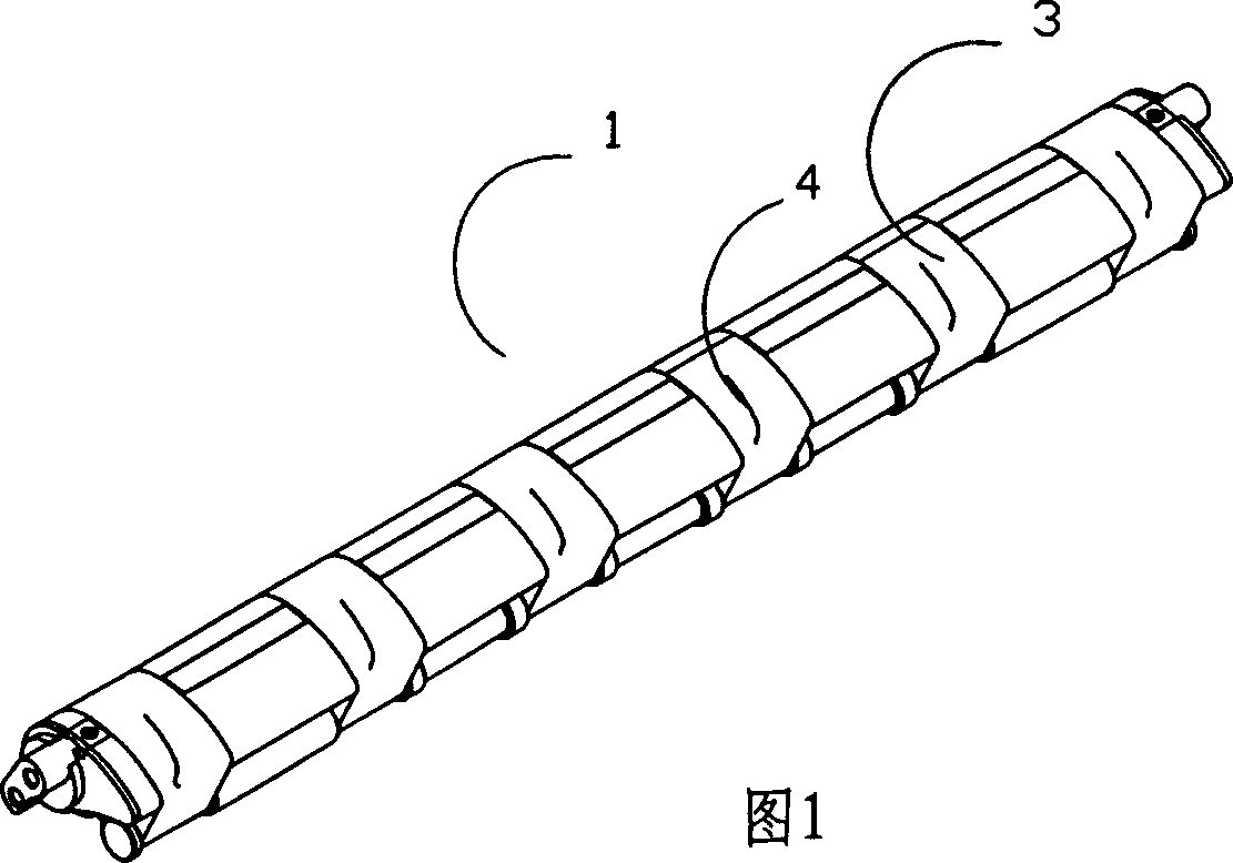
[0004] The existing collecting tube is shown in Figure 1. There is a grid ring 3 on the collecting tube 1. At present, the negative pressure test must be performed on the corresponding suction seam 4 on the grid ring 3 after opening the cradle. Spinning needs to be stopped first. Carry out inspection again, and then spin the yarn after the inspection, so yarn breakage will inevitably occur, which will affect the quality of spinning, and at the same time, the yarn must be re-spliced, resulting in low production efficiency and troublesome operation

Method used


Image

  • Collecting tube with detection hole
  • Collecting tube with detection hole
  • Collecting tube with detection hole

Examples


Embodiment Construction

[0019] The present invention will be further described in detail below in conjunction with the accompanying drawings and embodiments.

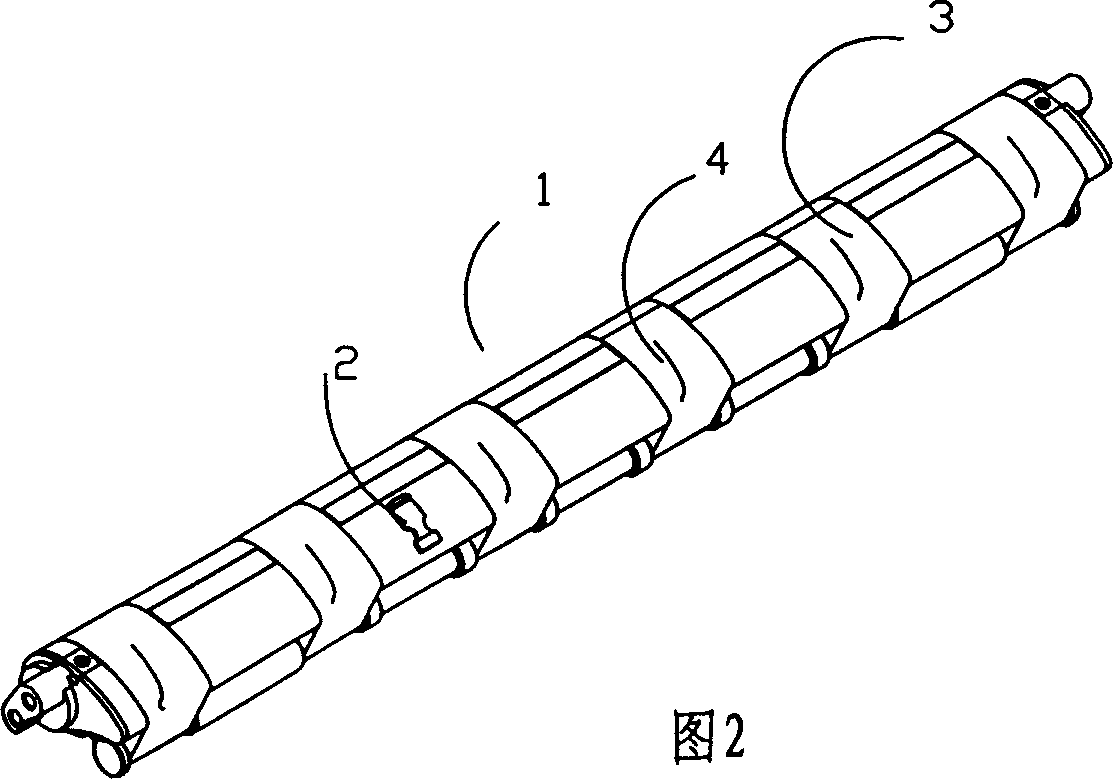
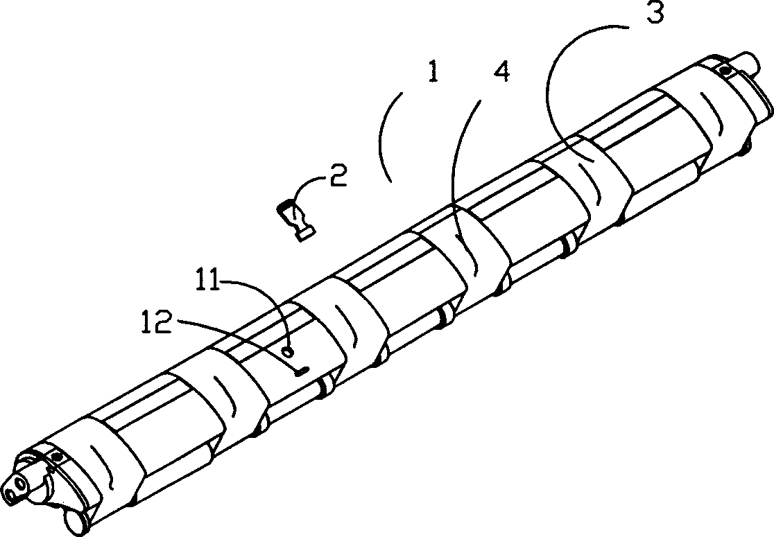
[0020] As shown in Figure 2, image 3 It is the collecting pipe 1 of the embodiment of the present invention. The collecting pipe 1 has a test hole 11 and a positioning hole 12 at the position away from the grid ring 3, and the corresponding sealing cover 2 has a sealing member 21 and a positioning member 22, and the positioning member 22 is inserted into the positioning In the hole 12, the sealing member 21 just covers the test hole 11.

[0021] The above-mentioned sealing member 21 is designed as a boss type, such as Figure 5 As shown, this facilitates better sealing of the test hole 11 of the collecting pipe 1 . It can also be designed into a flat shape, which can still be sealed under negative pressure.

[0022] Above-mentioned locator 22 can be designed into various shapes, is designed as arrow-shaped in the present embodiment, see F...


PUM


Abstract

The invention discloses a collecting band pipe with detector hole of collecting basin fleece device, which is installed between spinning drafting system and twister. The invention is characterized by the following: installing unilateral test hole in the non-mesh coil motor area of collecting body by collecting pipe with test hole and body; sealing test hole by airtight cover; opening test hole directly to check negative pressure in spinning course; avoiding rechecked inappropriate operation; improving spinning quality and production efficiency; simplifying the operation.

Description

technical field [0001] The invention relates to a component of a spinning device, in particular to a collecting tube with a detection hole arranged in a device for collecting fiber strands between a spinning drafting device and a twisting device. Background technique [0002] In the traditional spinning device, the drafted fiber strands are directly connected to the output roller pair of the drafting device for twisting, and a so-called spinning triangle will appear on the nip line of the output roller pair, which will affect the production process. yarn quality. This is due to the fact that the drawn fiber strands leave the drafting device with a fixed width and are twisted together into a yarn with a smaller diameter. Therefore, in order to eliminate the spinning triangle, increase the strength of the yarn and reduce hairiness, a negative pressure area is often used between fiber drafting and spinning to achieve yarn accumulation. [0003] There are various ways to reali...

Claims


Application Information

Patent Timeline
IPC IPC(8): D01H5/72D01H13/26
Inventor 徐时平邬建明王卫
Owner NINGBO DECHANG PRECISION TEXTILE MACHINERY
Learn More