Construction process of cast-in-situ bored pile

A technology of bored piles and construction technology, which is applied to sheet pile walls, infrastructure engineering, construction, etc., can solve the problems of difficult removal of slag at the bottom of the pile, lowering the quality of the pile body, and prone to collapse holes, etc., so as to improve the pile body. Quality and operational efficiency, highlighting substantive features, avoiding the effect of pile diameter expansion

Inactive Publication Date: 2009-07-22
THE FIRST COMPARY OF CHINA EIGHTH ENG BUREAU LTD
View PDF0 Cites 39 Cited by
  • Summary
  • Abstract
  • Description
  • Claims
  • Application Information

AI Technical Summary

Problems solved by technology

[0002] At present, in the construction of pile foundations, the commonly used hole-forming methods are rotary drilling rig and mud retaining wall forming holes. The rotary drilling rig is suitable for soft soil layers. Using this technology, on the one hand, the hole-forming period is long, and a large amount of time is required within a limited time. The mechanical operation of the piles results in a narrow construction site. On the other hand, the soft soil layer is prone to hole collapse during the hole formation process. After the holes are formed, the diameter of the pile body expands seriously, and the sediment at the bottom of the pile is not easy to remove, which reduces the quality of the pile body. ; For the geological conditions of the weathered rock layer lying under the soft soil layer, if this process is adopted, when the drill bit encounters a large boulder or probe stone, it is easy to cause the drilling to deviate. At this time, earth and stone (sand or gravel) need to be filled Re-drilling greatly reduces the operating efficiency; the whole process of forming the hole uses mud to protect the wall, and the discharge of mud is relatively large, which causes certain pollution to the environment. This is the deficiency of the existing technology

Method used


Image

  • Construction process of cast-in-situ bored pile

Examples


Embodiment Construction

[0014] In order to clearly illustrate the technical characteristics of this solution, the following will describe this solution through specific implementation modes and in conjunction with the accompanying drawings.

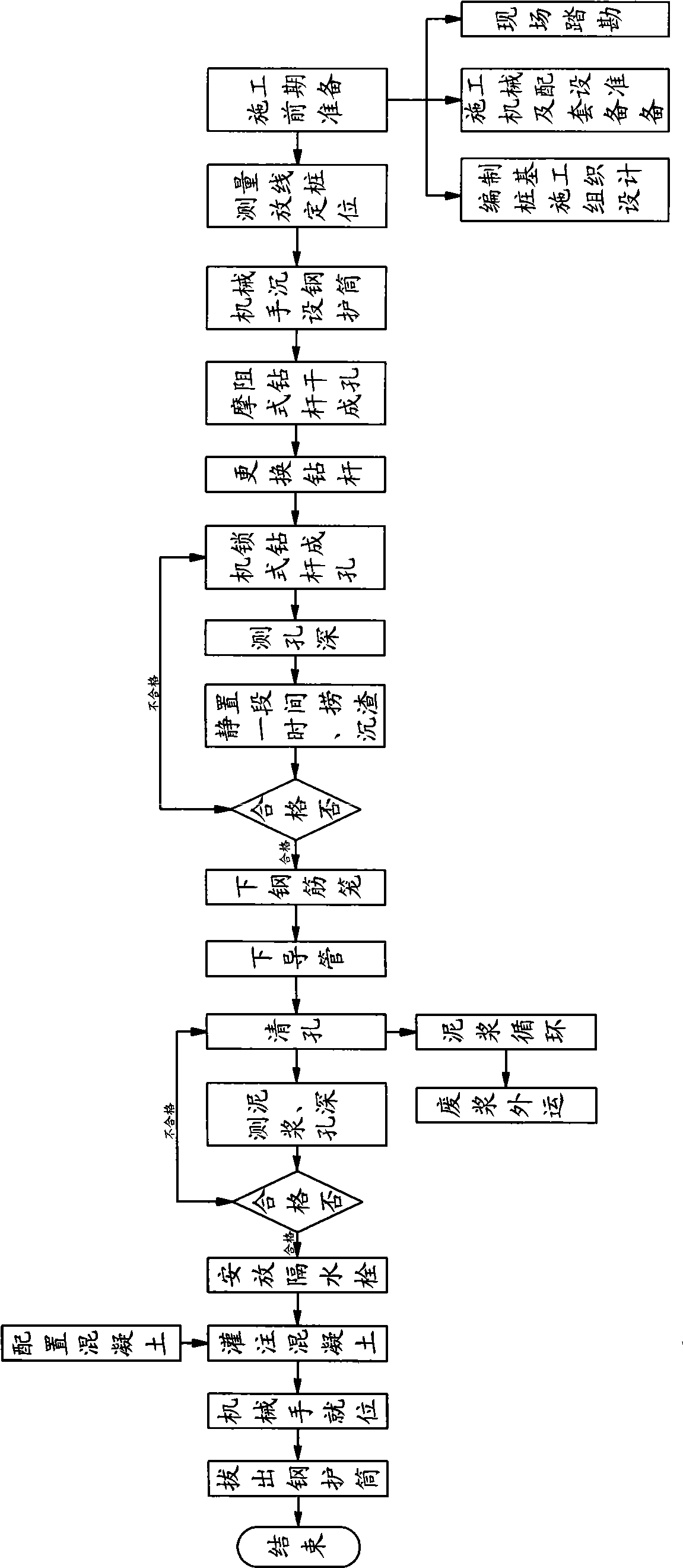
[0015] The construction technology of bored piles in this scheme includes the following steps:

[0016] (1) Set the steel casing: use the manipulator to place the steel casing, adjust the position and verticality, then vibrate and sink to the upper surface of the compact soil layer. The steel casing has an inner diameter 100mm larger than the pile diameter and a wall thickness Steel plate spiral welded pipe ≥8mm, length ≥7m, and the upper part of the steel casing has an overflow port.

[0017] (2) Hole forming: In the soft soil layer, a rotary drilling rig with a friction drill rod is used to dry the hole. The drill bit used when forming the hole is a rotary drilling bucket, and the diameter of the rotary drilling bucket is equal to the pile diameter. The soft ...


PUM


Abstract

The invention relates to a construction process for the pile foundation in the civil engineering, in particular to a construction process of a bored pouring pile. During the process, a steel casing is sunk on the upper surface of the dense soil layer at the soft soil layer section; the wall of the pile is protected by the steel casing; subsequently, a rotary excavation drilling machine with a friction-typed drilling rod is used for forming hole; at the dense soil layer section, the rotary excavation drilling machine with a lock-typed drilling rod is used for forming hole. Therefore, the boring deviation and diameter enlarging of the pile can be effectively avoided; the pile quality and the operation efficiency are improved; if the dense soil layer section contains the substance with plenty of underground water, the slurry is used for protecting the wall of the pile during the hole-forming process; after the hole is completed, the hole is arranged statically for certain a time; the sunk slag at the bottom of the pile is removed by a cylindrical drilling bucket; and if the dense soil layer contains the substance which has no underground water basically or has little underground, the dry hole-forming method is used. The construction process can avoid collapsing of the hole, reduces the displacement of the slurry and reduces the pollution to the environment.

Description

Technical field: [0001] The invention relates to a pile foundation construction technology in civil engineering, in particular to a bored cast-in-place pile construction technology. Background technique: [0002] At present, in the construction of pile foundations, the commonly used hole-forming methods are rotary drilling rig and mud retaining wall forming holes. The rotary drilling rig is suitable for soft soil layers. Using this technology, on the one hand, the hole-forming period is long, and a large amount of time is required within a limited time. The mechanical operation of the piles results in a narrow construction site. On the other hand, the soft soil layer is prone to hole collapse during the hole formation process. After the holes are formed, the diameter of the pile body expands seriously, and the sediment at the bottom of the pile is not easy to remove, which reduces the quality of the pile body. ; For the geological conditions of the weathered rock layer lying...

Claims


Application Information

Patent Timeline
Patent Type & Authority Applications(China)
IPC IPC(8): E02D5/38E02D15/04
Inventor 李迪安柴永征刘广文徐爱杰陈永伟秦家顺刘炳川赵海峰吕守龙和嘉张凤兰
Owner THE FIRST COMPARY OF CHINA EIGHTH ENG BUREAU LTD
Why Eureka
Try Eureka