High-power LED high-brightness lighting lamp

A high-power, lighting technology, applied in lighting devices, lighting and heating equipment, components of lighting devices, etc., can solve the problems of inability to meet the heat dissipation requirements of high-power LEDs, unsatisfactory heat dissipation, and poor use effects. Enhance the directional irradiation light intensity, improve the heat dissipation effect, and the effect of uniform light intensity

Inactive Publication Date: 2006-07-26
江苏江旭电子有限公司
View PDF5 Cites 44 Cited by
  • Summary
  • Abstract
  • Description
  • Claims
  • Application Information

AI Technical Summary

Problems solved by technology

Although this street lamp dissipates heat through enlarged heat dissipation fins, it only relies on natural heat dissipation. The actual heat dissipation is still not ideal, and it still cannot meet the heat dissipation requirements of high-power LEDs.
[0010] Since the heat dissipation problem of high-power and high-brightness LEDs has not been well resolved, it is greatly restricted from being used as high-brightness lighting, and the actual use effect is not good.
[0011] Furthermore, LEDs usually project the light sour

Method used


Image

  • High-power LED high-brightness lighting lamp
  • High-power LED high-brightness lighting lamp
  • High-power LED high-brightness lighting lamp

Examples


Embodiment 1

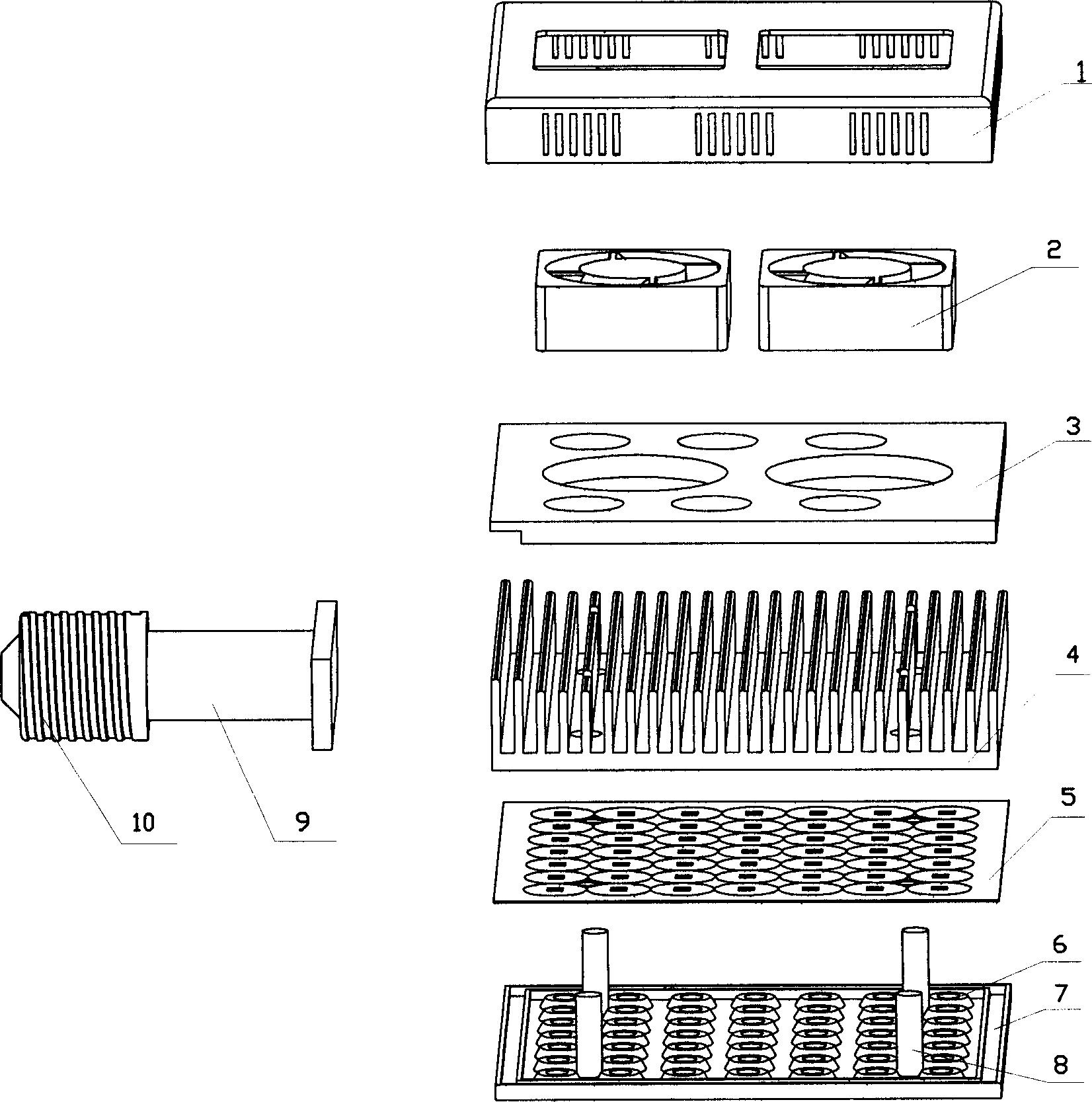
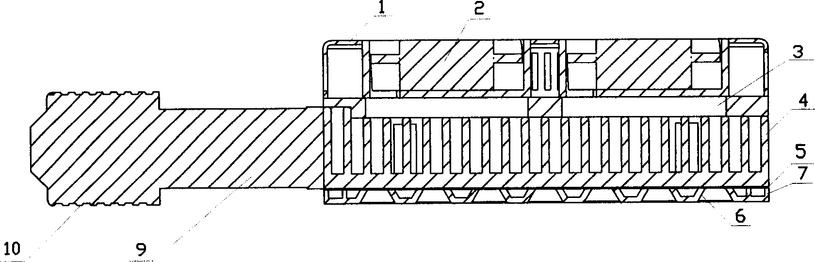
[0032] Embodiment 1: see Figure 1-Figure 7 , High-power LED high-brightness lighting street lamps, according to the direction of light projection, there are respectively fixed two cooling fans 2 Hollow cover 1 with heat dissipation windows, power supply mounting plate 3, aluminum heat dissipation plate with fins 4, LED light-emitting array 5 , the reflective bowl array 7 is superimposed and crimped with each other, and the screws are tightened to form, and the screw port of the handle 9 is fixed on the aluminum heat sink to connect the lamp holder 10.

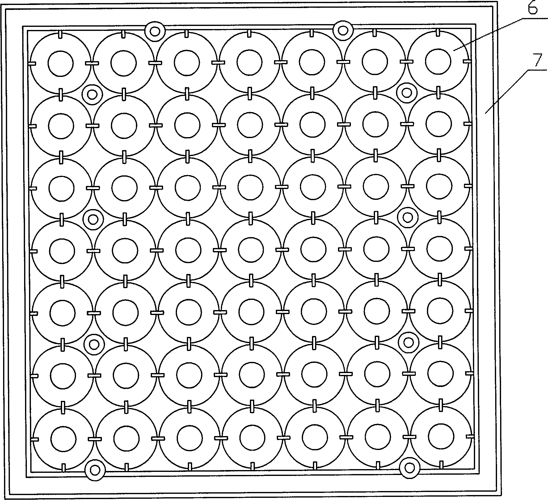
[0033] Wherein: the cooling fan 2 is a blowing fan; the reflective bowl array 7 ( image 3 , 4 ), which is integrally molded from plastic, and there are 7*7 reflective bowls 6 with 95-degree reflection angles regularly arranged at 20mm intervals in the center. The surface is coated with a silver-white reflective coating 11, and there are a number of protruding connecting columns 8 on the back, which are processed with Intern...

Embodiment 2

[0035] Example 2: see Figure 8, as in Example 1, the LED light-emitting array 5 has thermal conductive silicone grease 19 between the LED heat sink 13 on the back and the aluminum heat sink 4, so that heat conduction contact without air gaps is formed between the heat sinks of each light-emitting unit and the heat sink, which can further reduce the heat dissipation. Small thermal resistance, enhance heat dissipation effect.

[0036] In the street lamp test of the embodiment, the illuminance at 8 meters and 10 meters can reach 30lx and 20lx respectively, the color rendering index is 81, and the color temperature is 5570, which can completely replace the existing lighting street lamps.


PUM


Abstract

The invention relates to an improvement on the LED high power lighting lamp, which is characterized in that: it is formed by a LED light array, a front reflective bowl array board relative to the LED array chip, a back metal heat emission board with heat emission wings, and a cooling fan. Wherein, the LED light array is formed by arranging the LED light units on the insulation circuit board, while the LED light units comprises the LED chips mounted on the metal heat emission swings with insulation layers; the LED chip has a outside transparent cover with reflective bowl. The invention has two-stage heat conduction and heat emission, while it adds the fan to emit heat and improve the LED heat emission efficiency; the LED chip two-stage reflective bowl can centralize the light, improve the brightness, enlarge the lighting angle and meet the demand of lighting large area. The invention can solve the problems of high power LED high brightness light lamp, which it can be used in high suspended street lamp with enough brightness.

Description

technical field [0001] The invention relates to an energy-saving, long-life and high-brightness illuminating lamp, especially a high-brightness illuminating lamp with high-power LED and low power consumption. Background technique [0002] LED has the advantages of extremely high power rate, long life, and good shock resistance. Therefore, LED light-emitting components with long service life, power saving, low working voltage, and good safety are developed and used to replace tungsten filament light-emitting incandescent lamps for high-temperature lighting. Brightness lighting is pursued by people. [0003] Chinese patent CN2524072Y discloses a solar elevated street lamp device, which installs a plurality of LEDs in a square cone-shaped light collector, and sets a mirror reflector on its side, so that each LED bends toward the adjacent mirror surface, thereby improving the reflection and light-gathering ability . [0004] The solar LED street lamp disclosed in Chinese paten...

Claims


Application Information

Patent Timeline
IPC IPC(8): F21S4/00F21V29/02F21V7/22F21Y101/02F21V29/60F21V29/74F21V29/89F21Y115/10
Inventor 罗正良张再平苏克强
Owner 江苏江旭电子有限公司
Why Eureka
Try Eureka