AC generator for vehicle
A technology for alternators and vehicles, which is applied in the direction of electrical components, electromechanical devices, electric components, etc. It can solve the problems of reduced insulation performance, hindering the heat dissipation of conductors, and practical impossibility, so as to reduce the axial height and improve the electric resistance Chemical corrosion resistance, effect of securing insulation
- Summary
- Abstract
- Description
- Claims
- Application Information
AI Technical Summary
Problems solved by technology
Method used
Image

Examples
Embodiment approach 1
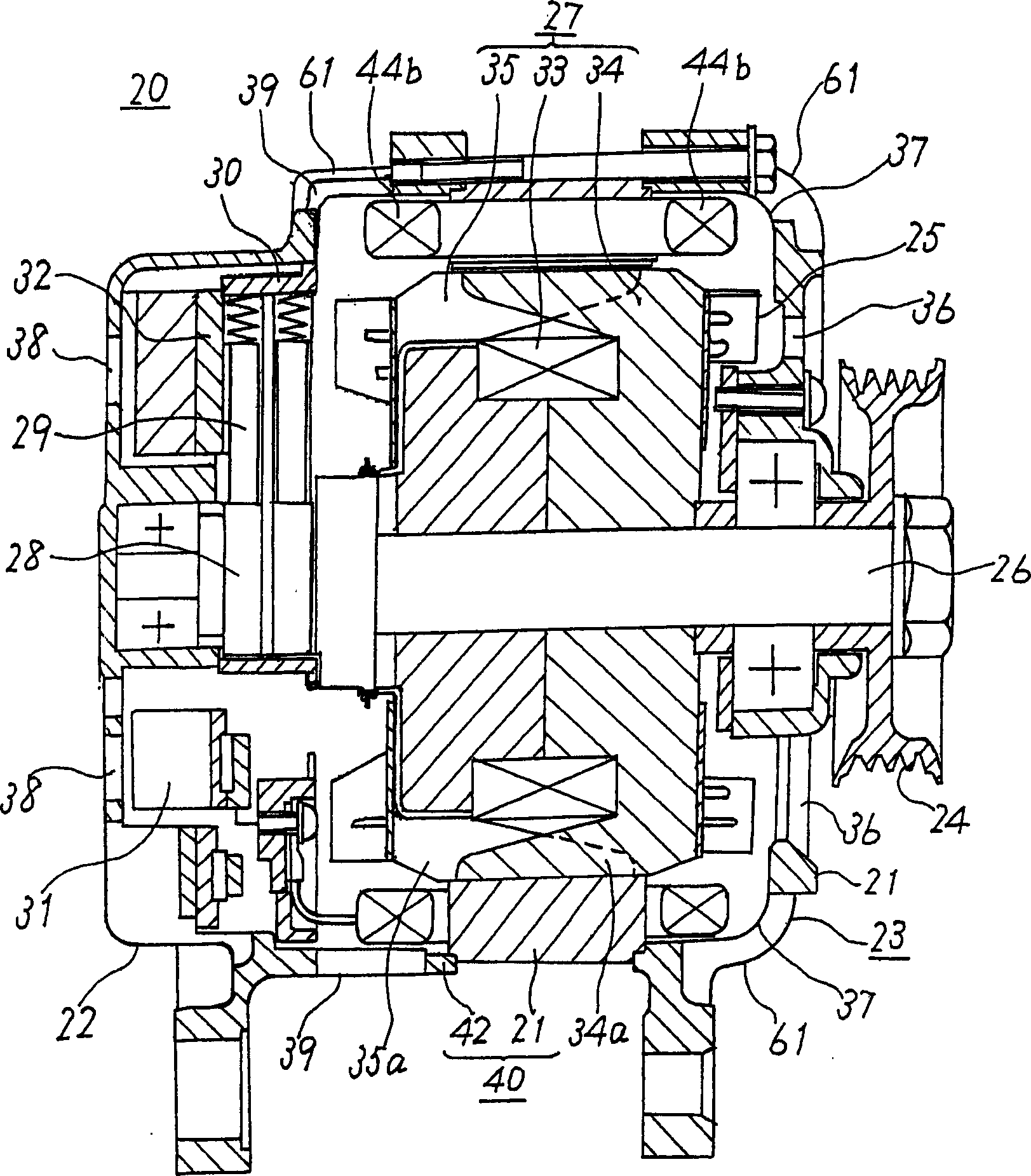
[0018] Now refer to figure 1 The automotive alternator according to Embodiment 1 of the present invention will be described.
[0019] The car uses an alternator 20 such as figure 1 As shown, it includes: a front bearing frame 21 made of approximately bowl-shaped aluminum with good heat transfer performance and a casing 23 made of a rear bearing frame 22; it is arranged in the casing 23 and a pulley 24 is fixed at one end. shaft 26; a drum (rundle) rotor 27 fixed to the shaft 26; a fan 25 fixed to both axial ends of the rotor 27; a stator 40 fixed to the casing 23 as surrounding the rotor 27; The slip ring 28 that supplies current to the rotor 27 at the other end of the above-mentioned shaft 26; a pair of brushes 29 that slide on the surface of the slip ring 28; the brush holder 30 that places the brush 29; is electrically connected with the stator 40 and will A rectifier 31 for rectifying the alternating current generated on the stator 40 into a direct current;
[0020] The...
Embodiment approach 2
[0032] According to Embodiment 2, such as Figure 6 As shown, before inserting into the slot 41c, the slot placement portion 44a of the coil unit is made into an approximately rectangular cross-section with the short side in the radial direction and the long side in the circumferential direction, and is arranged in two rows close to each other in the radial direction. In addition, in the figure, 47 represents the insulating resin impregnated in order to form the above-mentioned coil unit.
[0033] In this way, since the conductor of the groove placement portion 44a can be placed in the circumferential direction in the groove 41c without gaps, at this time, at the position where the insulating coating layer is thinned and the circumferential direction is the long side, it can also be placed along the radial direction. Arranging the aforementioned conductors closely increases the density of the conductors in the slot 41c, so that the heat generated by the conductors can be effic...
Embodiment approach 3
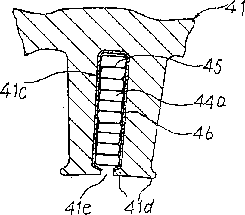
[0035] According to Embodiment 3, it is constituted as, for example Figure 7 As shown, before being inserted into the slot 41c, the slot placement portion 44a of the coil unit is made into an approximately rectangular cross-section with the long side in the radial direction and the short side in the circumferential direction, and is arranged in a row close to each other in the radial direction. Also in this way, the conductors of the groove placement portion 44a can be placed in the circumferential direction in the groove 41c without gaps.
[0036] In this case, since the insulating coating layer is thinned at the long sides in the radial direction, the heat transfer surfaces at both ends of the tooth-shaped portion of the laminated core can be ensured at the long sides in the radial direction. , because the heat of the armature coil generated by power generation is effectively dissipated to the outer circle side of the laminated core through the two ends of the tooth-shaped ...
PUM
 Abstract
Description
Claims
Application Information
 - R&D
- Intellectual Property
- Life Sciences
- Materials
- Tech Scout
- Unparalleled Data Quality
- Higher Quality Content
- 60% Fewer Hallucinations
Browse by: Latest US Patents, China's latest patents, Technical Efficacy Thesaurus, Application Domain, Technology Topic, Popular Technical Reports.
© 2025 PatSnap. All rights reserved.Legal|Privacy policy|Modern Slavery Act Transparency Statement|Sitemap|About US| Contact US: help@patsnap.com