

Supersonic process of treating organic waste water
A technology of organic wastewater and ultrasonic waves, applied in the direction of mechanical oscillation water/sewage treatment, etc., can solve the problems of insufficient effect of cavitation energy and low conversion rate of sound energy into cavitation energy, so as to reduce energy consumption and improve utilization rate , Improve the effect of processing effect
- Summary
- Abstract
- Description
- Claims
- Application Information
AI Technical Summary
Problems solved by technology
Method used
Image

Examples
Embodiment 1
[0027] The organic matter in the waste water is trichloropropane with a concentration of 800mg / l.
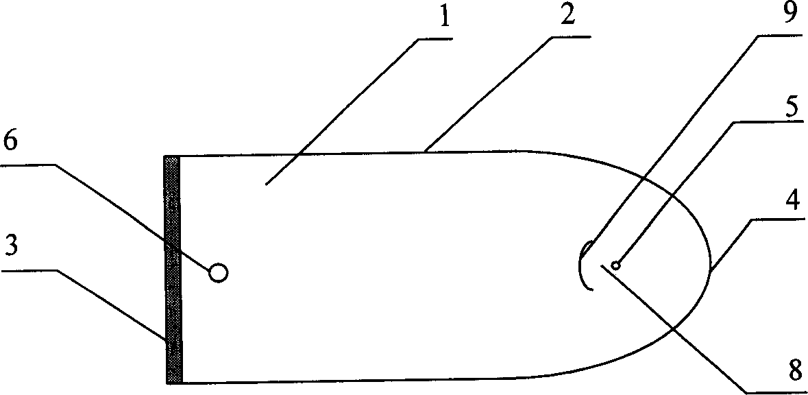
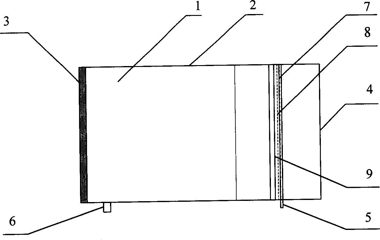
[0028] The reactor 1 comprises: a shell 2, an ultrasonic generating device 3, a focusing reflection plate 4, a water inlet pipe 5, and a water outlet 6 (see figure 1 , figure 2 ).
[0029] The shell 2 of the reactor 1 is a box body, and the height of the box body is 0.5 meters. The cross-section of the box is composed of two parts, the left part is a rectangle with an unsealed right end, the length of the rectangle is 0.6 meters, and the width is 0.5 meters; the right part is a parabola with an opening facing the left, passing through the parabola apex The axis of is parallel to the length side of the left rectangle and exactly at the midpoint of the width side of the rectangle. With the vertex of the parabola as the origin (0, 0), the shape of the parabola is y 2 =-0.6x, the focus of the parabola is at (-0.15, 0), and the rectangle and the parabola meet at (-0.104, 0.25), ...
Embodiment 2
[0035] The organic matter in the waste water is trichloropropane with a concentration of 800mg / l.
[0036] The shell 2 of the reactor 1, the ultrasonic generating device 3, the focusing reflection plate 4, the water inlet pipe 5, and the water outlet 6 are the same as those of the embodiment 1 (see figure 1 , figure 2 ).
[0037] A baffle 9 is provided in the reactor 1 . The baffle plate 9 is a vertical plate parallel to the water inlet pipe 5, and is arranged on the side of the parabolic cylinder focus line 8 close to the ultrasonic generator 3; The arc is facing the water inlet direction of the water inlet pipe 5; the angle formed between the two ends of the arc and the center of the water inlet pipe is 60°, the radius of the arc is 0.06 meters, and the focus of the parabolic cylinder is between the arc and the water inlet pipe 5. The distance from the focal point to the center of the water inlet pipe is 0.03 meters; the height of the baffle plate 9 is the same as the le...
Embodiment 3~5
[0040] The reactor form that waste water treatment adopts and treatment condition are identical with embodiment 2, and the organic matter in the waste water is trichloropropane, and its concentration is respectively 100mg / l, 500mg / l, 1500mg / l, and the removal rate of trichloropropane after treatment is respectively 83%, 81%, 76%.
PUM
| Property | Measurement | Unit |
|---|---|---|
| Height | aaaaa | aaaaa |
| Length | aaaaa | aaaaa |
| Width | aaaaa | aaaaa |
Abstract
Description
Claims
Application Information