Mini-size engine

An engine and micro technology, applied in combustion engines, machines/engines, internal combustion piston engines, etc., can solve the problems of thermal efficiency and output power without ultra-high energy density, and it is difficult to ensure the establishment of mechanical similarity and thermal similarity.

Inactive Publication Date: 2006-08-09
CHONGQING UNIV
View PDF0 Cites 1 Cited by
  • Summary
  • Abstract
  • Description
  • Claims
  • Application Information

AI Technical Summary

Problems solved by technology

However, the essence of the micro-engine is to shrink the structure of the macro-scale heat engine. The establishment of the corresponding macroscopic heat engine in terms of mechanical similarity and thermal similarity, and its experimental results also prove that its thermal efficiency and output power are far from meeting the requirements of ultra-high energy density (expected output power 125w, actual output power 2.7w)

Method used


Image

  • Mini-size engine
  • Mini-size engine
  • Mini-size engine

Examples


Embodiment Construction

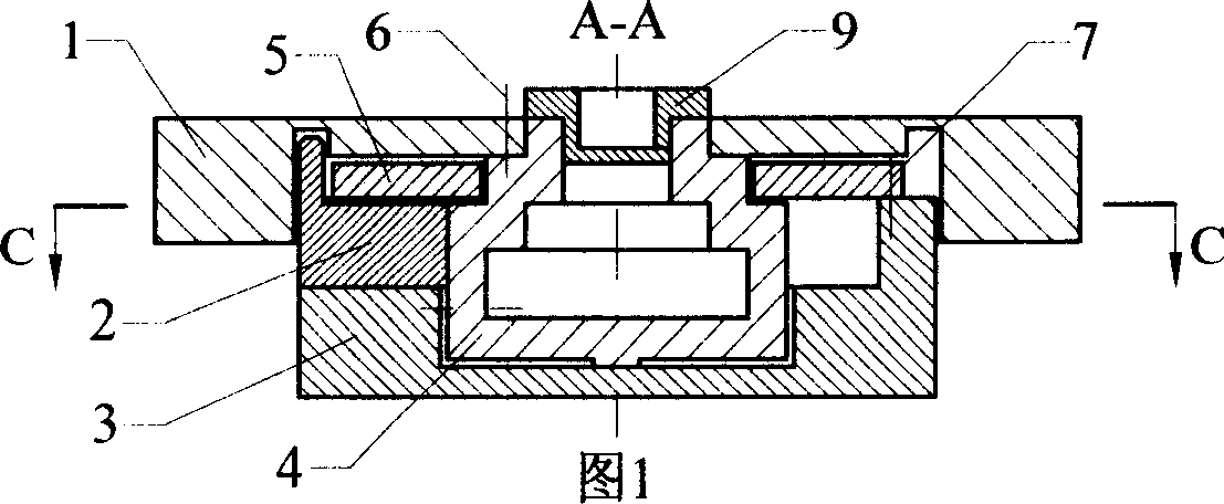
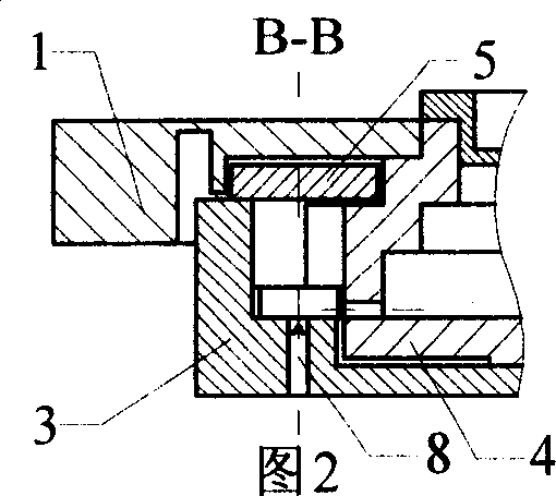
[0030] Below in conjunction with accompanying drawing, micro-engine of the present invention is described in further detail.

[0031] The micro-engine comprises an inner cam flywheel disc 1, a slide block 2, a cylinder body 3, a piston rotating shaft 4, a cover plate 5, an air transmission mechanism 9 and a probe type spark plug 8. Figure 1~ Figure 4 It shows the positional relationship of each part of the engine when the intake air is combusted. There is a fan-shaped bump type piston on the circumference of the middle part of the side of the piston shaft 4. The center line of the piston is parallel to the horizontal line. The center line of 2 is located on the horizontal center line of the piston shaft and the right side of the slider 2 is movably matched with the outer side of the piston shaft 4; the slider 2 can only slide horizontally in the square slot of the cylinder body 3, and the sliding The upper end of the cylindrical pin on the block 2 is located in the annular g...


PUM

PropertyMeasurementUnit
Angleaaaaaaaaaa
Outer radiusaaaaaaaaaa

Abstract

A tiny engine, in particular a tiny engine based on quasi - forces of gas flow circulating principle makes motor outputting power reach superhigh energy density. Tiny engine includes inner cam flywheel disk, slipper, cylinder body, piston rotor shaft, cover board, gas transmission mechanism and probe type spark plug. Said space in piston rotor shaft is premixing chamber for feeding high pressure gas fuel to cylinder body firing chamber, thereby realizing the thermodynamics effect through pre-set premix high pressure gas fuel form to substitute perfect gas power cycle constant entropy adiabatic compression process. Said invention has higher output loop net work, higher energy density and more simple system structure.

Description

technical field [0001] The invention relates to an engine, especially a micro engine based on the principle of quasi-gas power cycle. Background technique [0002] In recent years, the development of high-energy MEMS in the world is very rapid. At the International Mechanical Engineering Conference held in New York, USA in 2001, the article MEMS-23924 introduced a miniature rotary Wankel engine developed by the University of California in the United States. The triangular rotor rotating in the inner cavity is composed of a gas delivery mechanism and a probe type spark plug; due to the use of an eccentric device, there is a certain position offset between the center line of the rotor and the center line of the inner cavity, when the rotor revolves around the center of the eccentric device When rotating, the three vertices of the rotor are always in contact with the side wall of the inner cavity and form three closed combustion chambers; since the rotor and the eccentric devi...

Claims


Application Information

Patent Timeline
IPC IPC(8): F02B53/10F02B53/02
CPCY02T10/17Y02T10/12
Inventor 张力陈卫军李坚
Owner CHONGQING UNIV
Why Eureka
Try Eureka