Surge limiter for a traction power converter

A rectifier and overvoltage technology, applied in the field of overvoltage devices, can solve the problems of double-layer capacitor damage, manufacturing tolerance, and mutual drift of double-layer capacitor operating voltages.

Inactive Publication Date: 2006-08-09
SIEMENS AG
View PDF0 Cites 10 Cited by
  • Summary
  • Abstract
  • Description
  • Claims
  • Application Information

AI Technical Summary

Problems solved by technology

[0008] 1. Destructive, electrolyte-decomposing processes that occur when a special "maximum operating voltage" is exceeded
[0009] 2. Due to manufacturing tolerances, double layer capacitors of the same type may have different self-discharge and different internal resistance
As a result, when double-layer capacitors are con

Method used


Image

  • Surge limiter for a traction power converter
  • Surge limiter for a traction power converter

Examples


Embodiment Construction

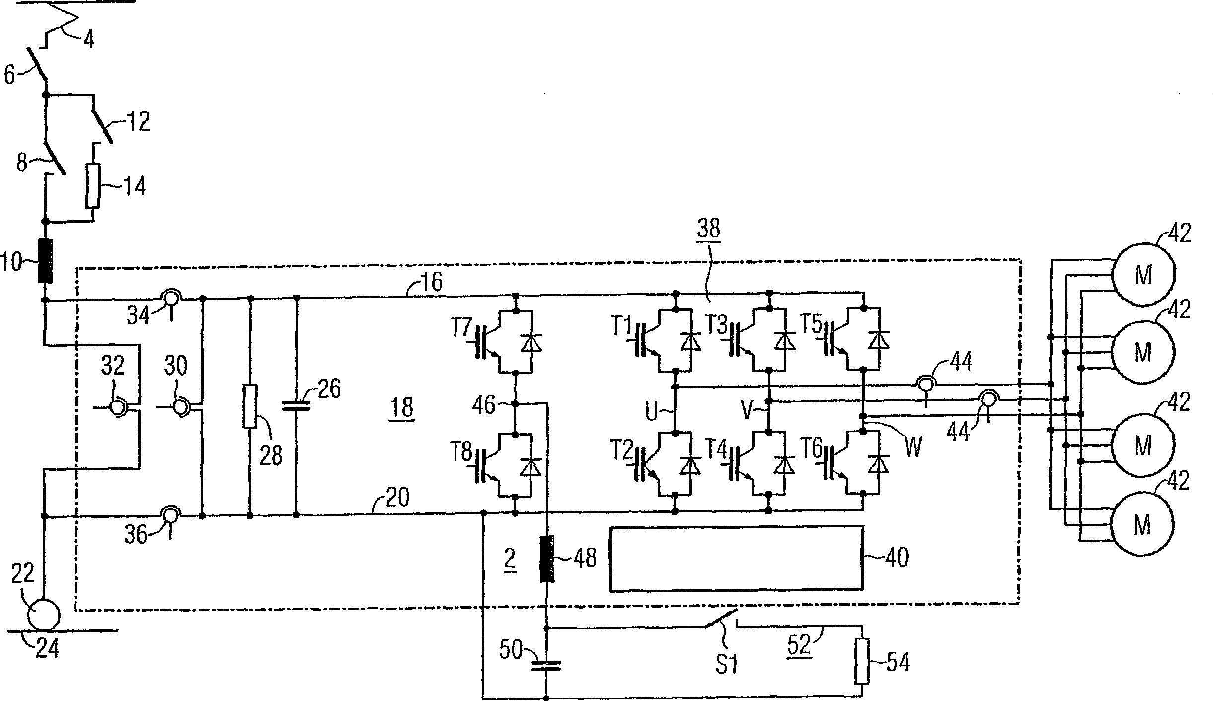
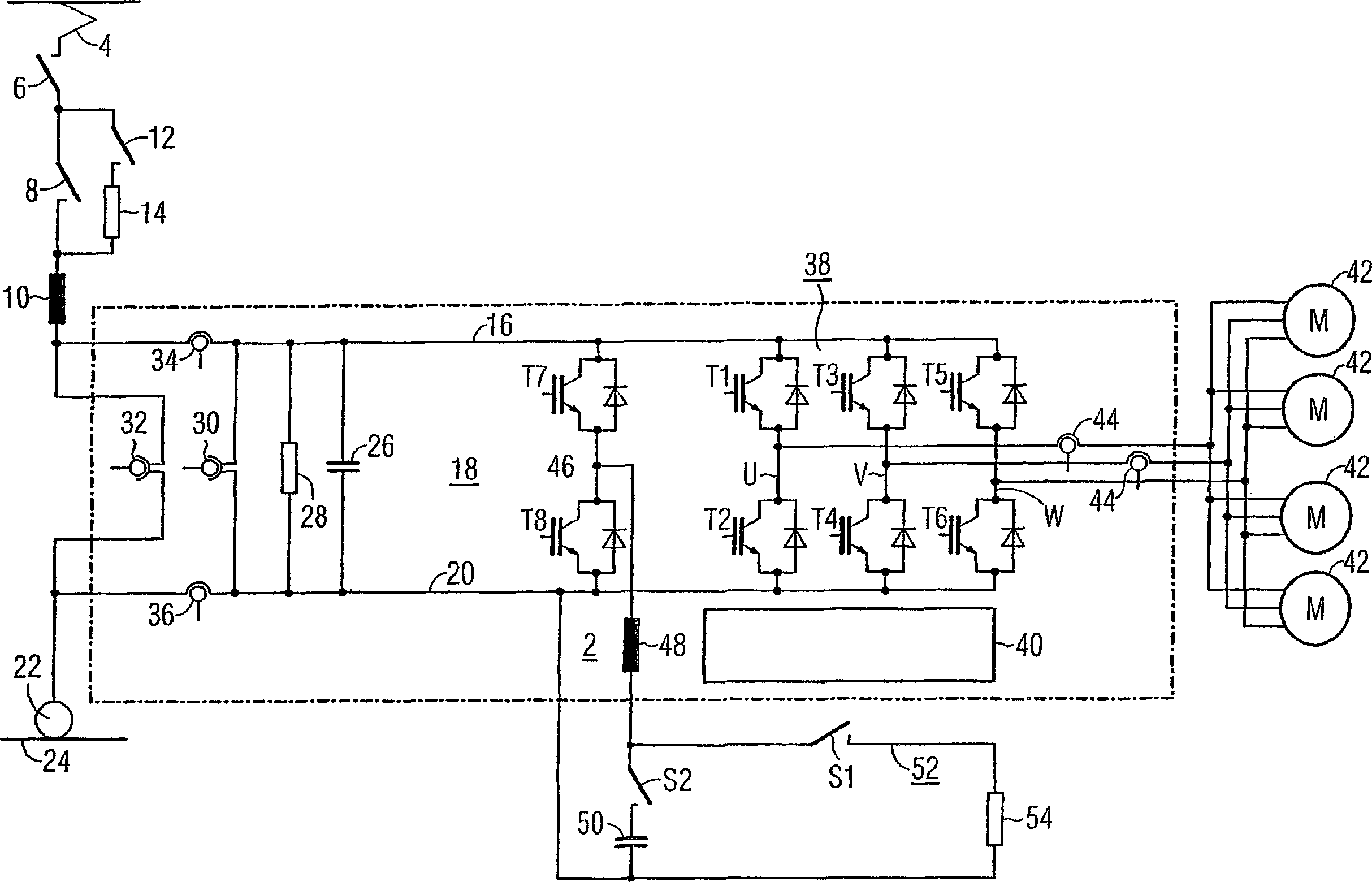
[0021] exist figure 1 The main current connection diagram of the traction rectifier of the fuel locomotive with the device 2 of the present invention is shown in detail. On the input side, the consumer 4 is connected to a network inductor 10 by means of a circuit breaker 6 and a network relay 8 . A series circuit of a charging relay 12 and a precharging resistor 14 is connected in parallel to the network relay 8 . The second connection of the network inductor 10 is connected to the positive busbar 16 of the intermediate circuit 18 of the traction rectifier. Negative busbar 20 is electrically conductively connected to busbar 24 by means of pulley 22 . The intermediate circuit 18 comprises an intermediate circuit capacitor 26 , a discharge resistor 28 , an intermediate circuit transformer 30 , a network transformer 32 , two converters 34 and 36 , and the device 2 according to the invention. The intermediate circuit capacitor 26 , the discharge resistor 28 , the intermediate c...


PUM


Abstract

The invention relates to a device (2) for limiting an overvoltage in the DC link (18) of a traction power converter. The inventive device (2) comprises two interruptible semiconductor switches (T7, T8) that are electrically connected in series, an inductor (48), a double-layer capacitor (50), and a resistor (54) which can be connected by means of a switch (S1). The inductor (48) and the double-layer capacitor (50) are electrically connected in series while said series connection is connected between an interconnection point (46) of the two interruptible semiconductor switches (T7, T8) and a negative conductor rail (20) of the DC link (18). Additionally, the connectable resistor (54) can be electrically connected parallel to the double-layer capacitor (50), resulting in a device which is structured in a particularly simple manner and by means of which overvoltages occurring in the DC link (18) of a traction power converter can be suppressed.

Description

technical field [0001] The invention relates to a device for limiting overvoltages in the intermediate circuit of a traction rectifier. Background technique [0002] Traction rectifiers, in particular traction rectifiers for diesel locomotives, usually have a pulse inverter which feeds at least one induction machine, especially an asynchronous machine. During driving, power is extracted from the energy supply network, in particular a railway network, and transmitted to the induction motor by means of a pulse inverter. The power flow is reversed during electric braking operation. Since the railway network cannot receive braking energy at every moment, an additional device for dissipating braking energy must be installed in the intermediate circuit. [0003] Furthermore, in the intermediate circuit of the traction rectifier there is provided a device for limiting the overcurrent which is primarily required to protect the pulsed inverter. Rapid overvoltages which arise, for ...

Claims


Application Information

Patent Timeline
IPC IPC(8): B60L7/22
CPCB60L9/22B60L7/22B60L9/005B60L3/003B60L2200/26
Inventor 马克-马赛厄斯·巴克兰马赛厄斯·霍夫斯泰特
Owner SIEMENS AG
Why Eureka
Try Eureka