Light core structural member for filling cast-in-situs reinforcing bar concrete

A reinforced concrete, light-weight technology, applied in the direction of building components, building structures, building materials, etc., can solve the problems of unfavorable earthquake resistance and material saving, heavy floor weight, inconvenient production, etc., to achieve light weight, reduced weight, The effect of convenient selection

Inactive Publication Date: 2006-08-16
邱则有
View PDF2 Cites 0 Cited by
  • Summary
  • Abstract
  • Description
  • Claims
  • Application Information

AI Technical Summary

Problems solved by technology

However, after this type of formwork member is used as a carcass in the cast-in-place reinforced concrete hollow structure floor, the weight of the formed floor is still relatively heavy, which is not conducive to earthquake resistance and material saving. At the same time, the production is inconvenient and the cost is high. Therefore, the development of A new type of light-weight tire mold member for filling cast-in-place reinforced concrete has been urgently needed

Method used


Image

  • Light core structural member for filling cast-in-situs reinforcing bar concrete
  • Light core structural member for filling cast-in-situs reinforcing bar concrete
  • Light core structural member for filling cast-in-situs reinforcing bar concrete

Examples


Embodiment Construction

[0045] The present invention will be further described below in conjunction with drawings and embodiments.

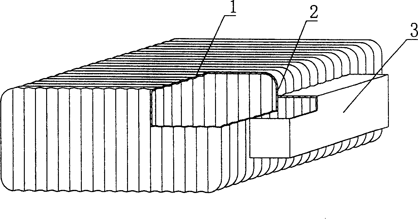
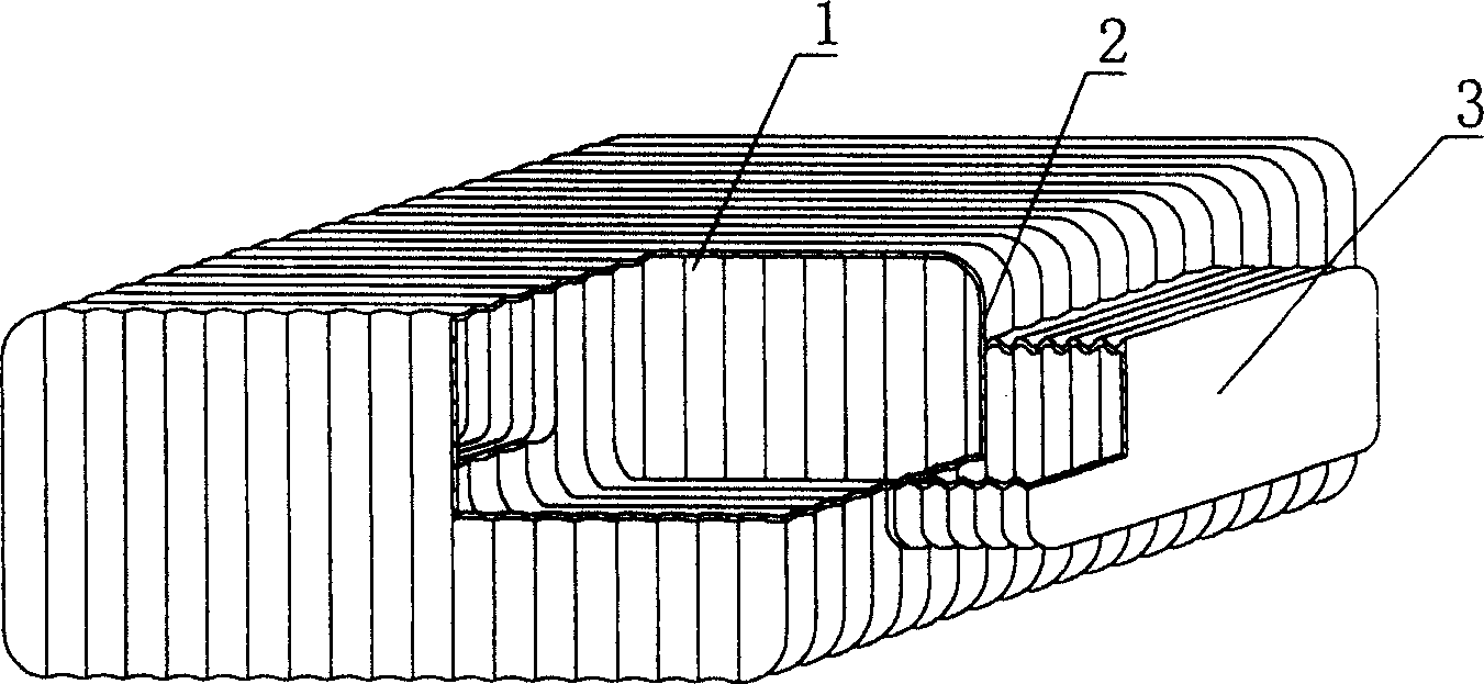
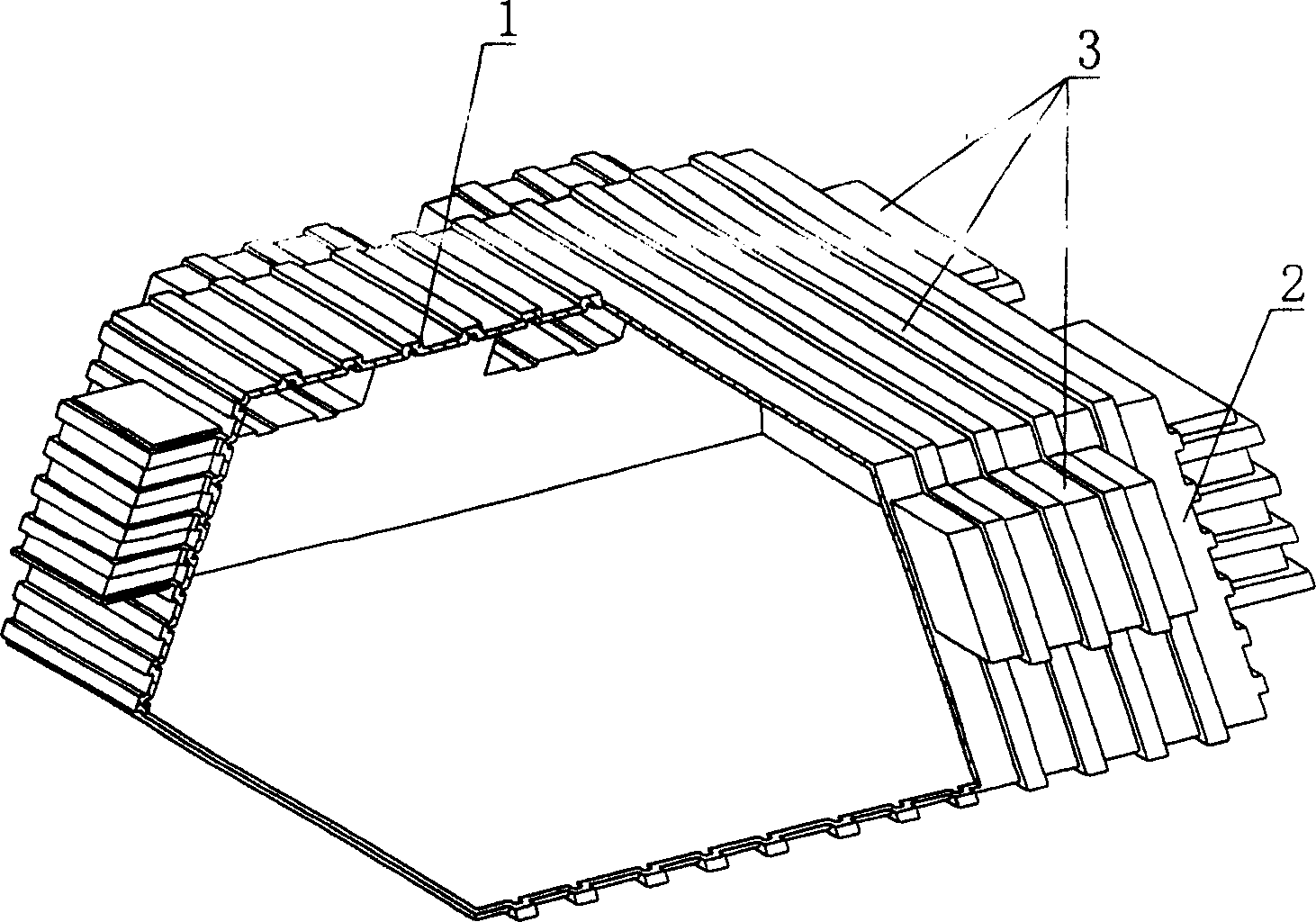
[0046] As shown in the drawings, the present invention includes a carcass 1, which is characterized in that the carcass 1 is a corrugated carcass, and the corrugated carcass wraps a lightweight material 18 to form corrugations on the outer surface of the carcass 1. figure 1 It is a structural schematic diagram of Embodiment 1 of the present invention. In each accompanying drawing, 1 is a carcass, 2 is the side of the carcass, and 3 is a protruding module. In each accompanying drawing, those with the same number have the same description. Such as figure 1 Among them, the carcass 1 is a corrugated carcass, and there are protruding modules 3 on the side 2 of the corrugated carcass 1 . figure 2 It is a structural schematic diagram of Embodiment 2 of the present invention, and its module 3 is a corrugated module. Such as Figure 15 As shown, the corrugated carcass wraps...


PUM


Abstract

The cast-in-place reinforced concrete light hollow stuffing includes the stuffing. The said mold member features that it is a corrugated cavity with light filler in it. The present invention is suitable for various cast-in-place reinforced concrete floor slab, roofing, base plate, wall and open web bridge, especially cast-in-place reinforced concrete hollow no-beam floor slab.

Description

[0001] This application is a divisional application of an invention patent application with an application date of March 31, 2003, an application number of 03118189.9, and a title of "a light-weight tire mold component for filling cast-in-place reinforced concrete". (1) Technical field [0002] The invention relates to a lightweight tire mold component for filling cast-in-place reinforced concrete. (2) Background technology [0003] At present, most buildings with brick-concrete structure and frame structure use prefabricated hollow-core slabs as floor slabs, which have the advantages of fast construction speed and low cost. However, because there is no firm connection between two adjacent prefabricated hollow slabs, only cement mortar is used to fill the joints, so the integrity is poor, which is not conducive to earthquake resistance, and cracks and water seepage often occur in the gaps. In order to solve the above problems, many buildings adopt the method of cast-in-place...

Claims


Application Information

Patent Timeline
IPC IPC(8): E04B5/36E04B5/17E04C1/40
Inventor 邱则有
Owner 邱则有
Why Eureka
Try Eureka