
Micro-rotation top with double-stator electromagnetic suspension rotor

A technology of electromagnetic levitation and double stators, which is applied in the direction of rotating gyroscope, gyro effect for speed measurement, measuring device, etc. It can solve the problems of being thrown out, the eccentricity of the micro rotor speed, and the loss of rotation, etc., to increase the impact resistance Effect

Inactive Publication Date: 2006-08-16
SHANGHAI JIAO TONG UNIV
View PDF1 Cites 19 Cited by
  • Summary
  • Abstract
  • Description
  • Claims
  • Application Information

AI Technical Summary

Problems solved by technology

One of the reasons why the speed of the micro-rotor cannot be further increased is that there is an eccentricity when the micro-rotor rotates. With the increase of the speed, the centrifugal force of the micro-rotor increases, and finally the micro-rotor is thrown out under the action of the centrifugal force and loses stable rotation.

Method used


Image

  • Micro-rotation top with double-stator electromagnetic suspension rotor
  • Micro-rotation top with double-stator electromagnetic suspension rotor
  • Micro-rotation top with double-stator electromagnetic suspension rotor

Examples


Embodiment Construction

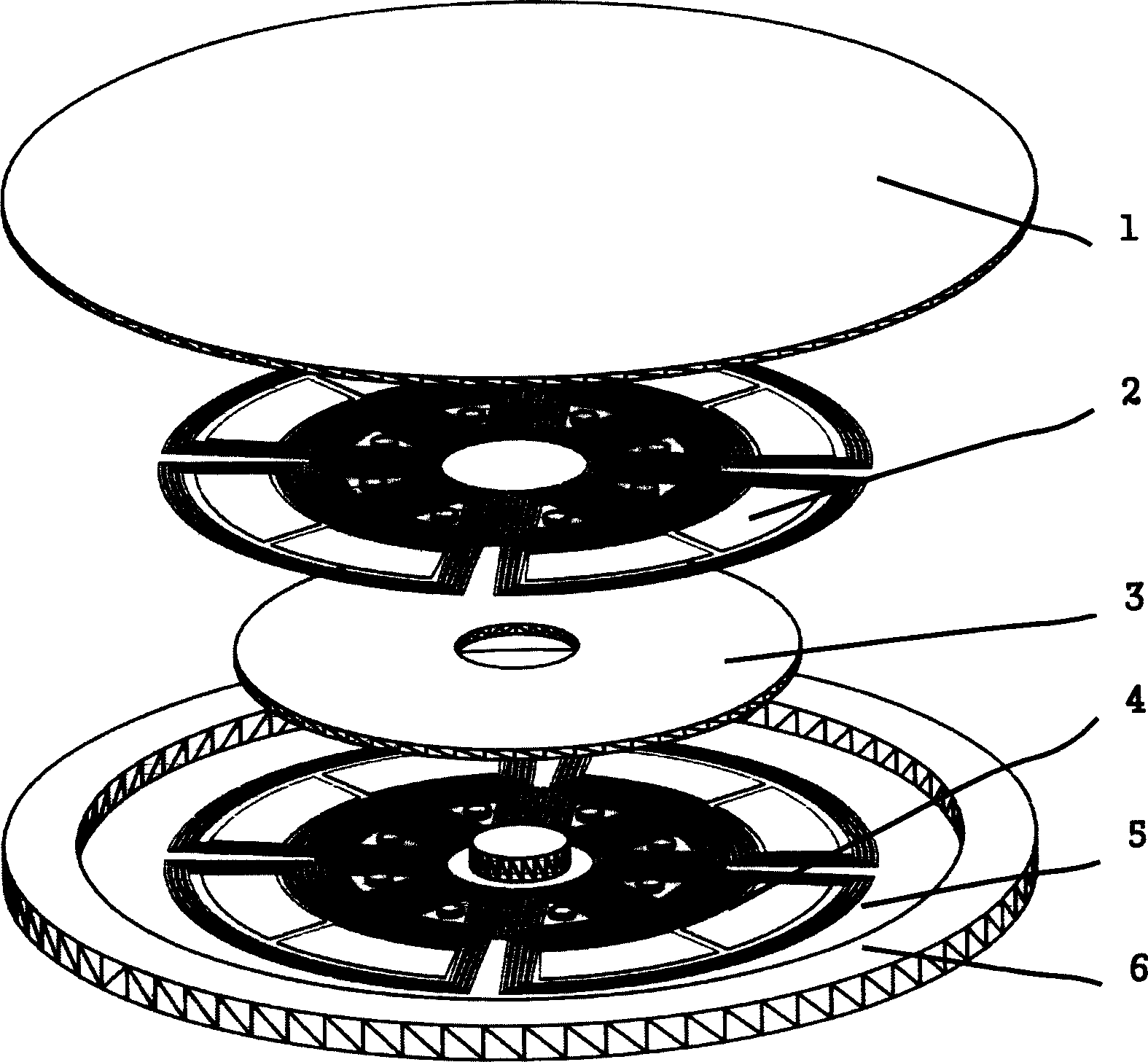
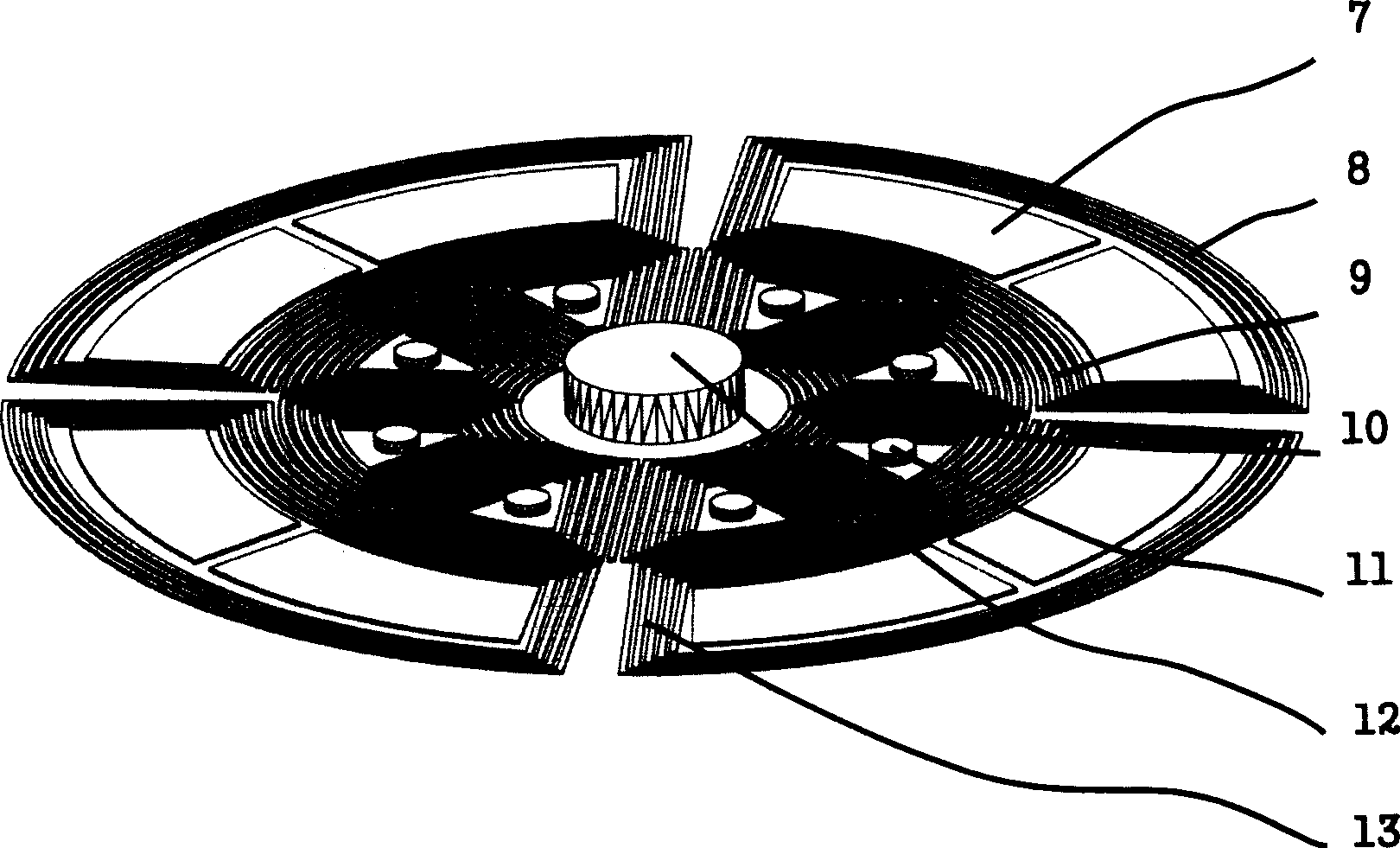
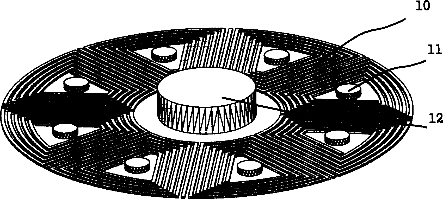
[0019] Such as figure 1 As shown, the present invention includes: an upper substrate 1 , an upper stator 2 , a micro-rotor 3 , a lower stator 4 , a lower substrate 5 , and a sealing ring 6 . The upper stator 2 is fabricated on the upper base body 1 by a microfabrication method, and forms a fixed connection with the upper base body 1 . The lower stator 4 is fabricated on the lower base body 5 by using a micro-machining method, and forms a fixed connection with the lower base body 5 . Except that the micro-rotor limiting post 12 is made on the lower stator 4, other structures of the lower stator 4 are exactly the same as the upper stator 2. A sealing ring 6 is fabricated on the outer edge of the lower base body 5 by microfabrication, and forms a fixed connection with the lower base body 5 . A fixed connection is formed between the sealing ring 6 and the upper base 1 by bonding. The micro-rotor 3 is stably suspended in the closed cavity formed by the upper base 1 , the lower b...


PUM


Abstract

A micro rotation gyroscope with double stator and electromagnetic suspension rotator consists of top base body, top stator, micro rotator, bottom stator, bottom base body and seal ring .It features that micro rotator is a conductive ring; rotary coil sensing electrode and suspension-stabilizing coil prepared by photo etching-plating are applied on top and bottom base bodies; the structure of top stator is completely the same as the structure of bottom stator except spacing column of micro rotator is set on bottom stator.

Description

technical field [0001] The invention relates to a device in the technical field of micro-electro-mechanical systems, in particular to a micro-rotating gyroscope with double-stator electromagnetic levitation rotors. Background technique [0002] In the past two decades, many kinds of micro-vibration gyroscopes have been processed by using silicon surface micro-processing technology or bulk micro-processing technology at home and abroad, but it is difficult for micro-vibration gyroscopes to achieve the high precision of traditional gyroscopes due to various reasons. In the 1990s, Shearwood and others proposed an electromagnetic levitation micro-rotating gyroscope. The electromagnetic levitation micro-rotating gyroscope is composed of planar coils, induction electrodes and micro-rotors. The planar coils are divided into suspension coils according to their functions. , rotating coil and stable coil. The electromagnetic levitation micro-rotating gyroscope is suspended and rotate...

Claims


Application Information

Patent Timeline
IPC IPC(8): G01C19/02G01C19/06G01P9/02
Inventor 陈文元吴校生赵小林张卫平
Owner SHANGHAI JIAO TONG UNIV
Learn More