
Calorimeter for bucket cover with closed circulation tube temperature control mechanism

A closed loop and calorimeter technology, applied in the field of calorimeters, can solve the problems of uncertain intensity, unrealistic, and poor reproducibility, and achieve the effects of enhanced stirring, strong reproducibility, and high accuracy

Inactive Publication Date: 2006-08-23
朱先德
View PDF0 Cites 5 Cited by
  • Summary
  • Abstract
  • Description
  • Claims
  • Application Information

AI Technical Summary

Problems solved by technology

However, the deficiencies in the prior art are: 1. There are too many uncertain factors in the ambient temperature under actual working conditions. How to make the measuring device quickly reach the ideal measuring temperature range in a certain environment is to check the quality of the measuring device. one of the conditions
In addition, the temperature of the inner barrel is not only directly affected by the temperature inside the outer barrel used to hold the inner barrel, but also indirectly affected by the ambient temperature outside the outer barrel. Therefore, it is necessary to stabilize the temperature of the outer wall of the outer barrel to a range close to the standard , and then adjust the temperature of the medium in the outer barrel to the most suitable temperature, so that the measuring device can quickly reach the temperature suitable for measurement and complete the measurement work; Realistically, the rise or fall of the ambient temperature will cause the outer barrel to absorb or release heat
Due to the different nature of endothermic and exothermic, and the degree of intensity is uncertain each time, the process is long. In this process, even if the temperature reading of the outer barrel is the same, the heat capacity of the instrument may vary greatly, resulting in a decrease in the accuracy of the test results and poor reproducibility. become worse

Method used


Image

  • Calorimeter for bucket cover with closed circulation tube temperature control mechanism
  • Calorimeter for bucket cover with closed circulation tube temperature control mechanism
  • Calorimeter for bucket cover with closed circulation tube temperature control mechanism

Examples


Embodiment 1

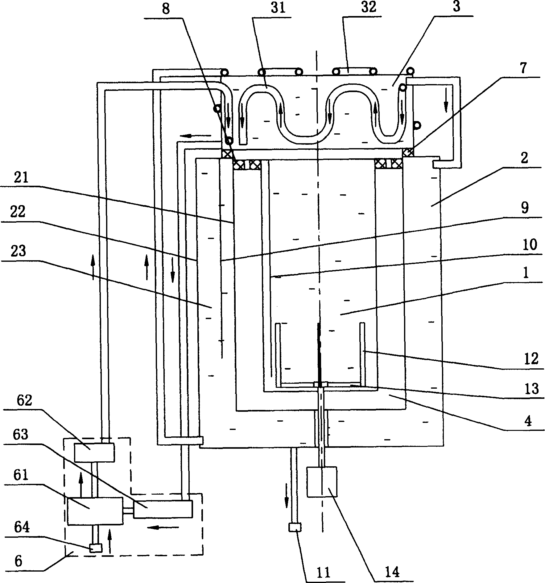
[0037] Embodiment 1: as figure 1As shown, a calorimeter with a closed loop temperature control mechanism in the lid of the present invention includes an inner barrel 1, an outer barrel 2 and a barrel lid 3 arranged on the top of the inner barrel 1 and the outer barrel 2, and the inner barrel 1 is placed in the outer barrel In 2, an outer barrel cavity 23 filled with a medium is formed between the outer side wall 22 and the inner side wall 21 of the outer barrel 2, and the medium can be liquid substances such as water and oil or other gaseous fluids; the inner barrel 1 and the outer barrel 2 There is an air interlayer 4 between them, the bung 3 is provided with a bung inner circulation pipe 31, the outer wall of the bung 3 is provided with a bung outer circulation pipe 32, the bung inner circulation pipe 31, the bung outer circulation pipe 32 and The circulation supply device 6 forms a closed-circuit circulation management and temperature control mechanism. The circulation sup...

Embodiment 2

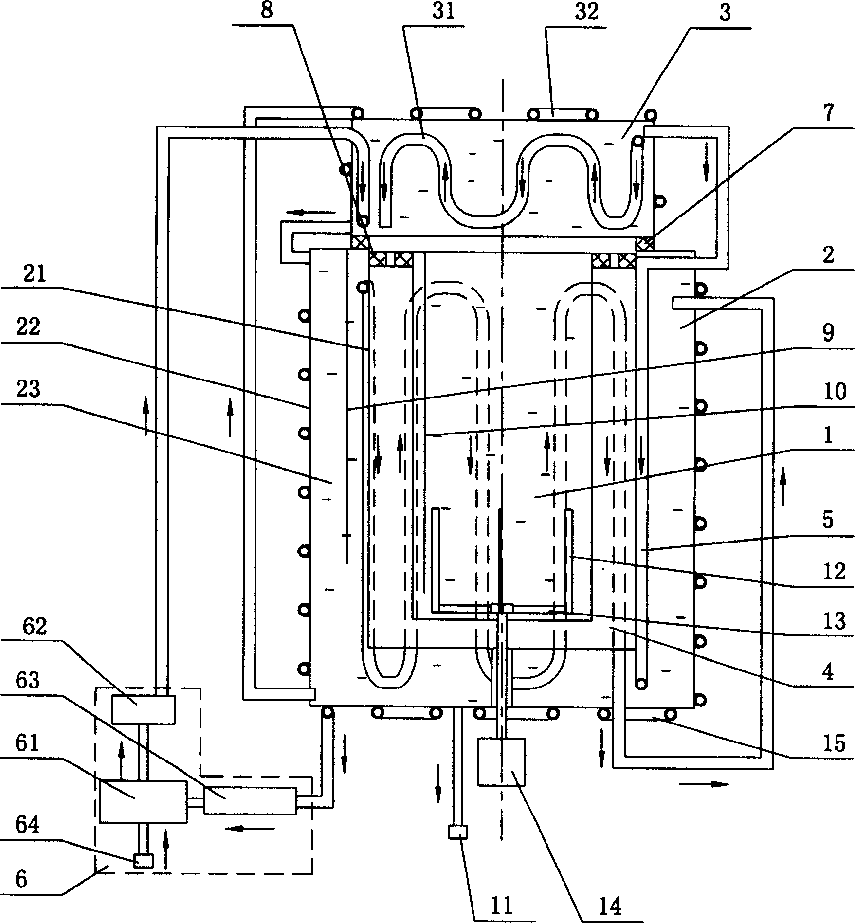
[0039] Embodiment 2: as figure 2 As shown, a calorimeter with a closed loop temperature control mechanism in the lid of the present invention includes an inner barrel 1, an outer barrel 2 and a barrel lid 3 arranged on the top of the inner barrel 1 and the outer barrel 2, and the inner barrel 1 is placed in the outer barrel 2, an outer barrel cavity 23 filled with medium is formed between the outer side wall 22 and the inner side wall 21 of the outer barrel 2, an air interlayer 4 is provided between the inner barrel 1 and the outer barrel 2, and an outer barrel cavity 23 is provided with an outer barrel cavity 23. Circulation pipe 5 in the barrel, outer barrel outer circulation pipe 15 is provided on the outer wall 22 of the outer barrel 2, inner circulation pipe 31 of the barrel lid 3 is arranged on the outer wall of the barrel lid 3, and outer circulation pipe of the barrel lid is installed on the outer wall of the barrel lid 3 32. The inner circulation pipe 5 of the outer ...

Embodiment 3

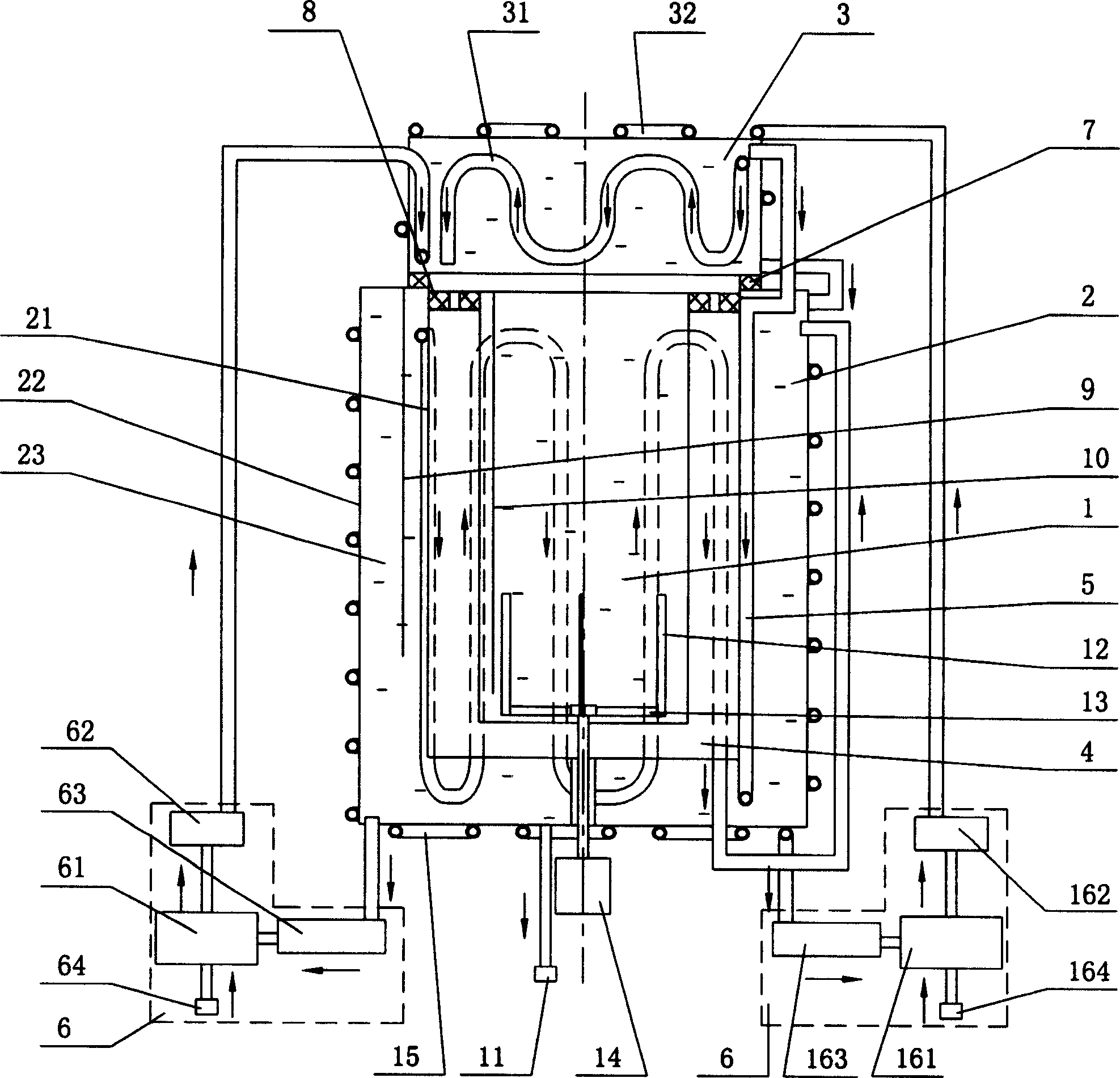
[0041] Embodiment 3: as image 3As shown, a calorimeter with a closed loop temperature control mechanism in the lid of the present invention includes an inner barrel 1, an outer barrel 2 and a barrel lid 3 arranged on the top of the inner barrel 1 and the outer barrel 2, and the inner barrel 1 is placed in the outer barrel 2, an outer barrel cavity 23 filled with medium is formed between the outer side wall 22 and the inner side wall 21 of the outer barrel 2, an air interlayer 4 is provided between the inner barrel 1 and the outer barrel 2, and an outer barrel cavity 23 is provided with an outer barrel cavity 23. Circulation pipe 5 in the barrel, outer barrel outer circulation pipe 15 is provided on the outer side wall 22 of the outer barrel 2, inner circulation pipe 31 of the barrel lid 3 is arranged on the outer side wall of the barrel lid 3, and outer circulation of the barrel lid is arranged on the outer side wall of the barrel lid 3 Pipe 32, outer barrel inner circulation...


PUM


Abstract

This invention discloses a calorimeter with a closed circuit circulation tube temperature control unit on the cover including an inner drum, an outer drum and a cover on their top, in which, the inner drum is set in the outer drum, a cavity containing medium is formed between the outside wall and the inside wall of the outer drum, an air interlayer is set between the inner drum and the outer drum, an internal circulation tube is set in the cover, an outside circulation tube is set on the outside wall of the cover and the internal circulation tube, the outer circulation tube and the circulation supply tube make up of a closed circuit circulation tube temperature control unit.

Description

technical field [0001] The invention mainly relates to a measuring instrument for measuring the calorific value of coal, oil or other exothermic substances in coal, petrochemical or electric power industries, in particular to a calorimeter with a barrel cover and a closed-loop temperature control mechanism. Background technique [0002] In the prior art, the measuring instruments used to determine the calorific value of substances are generally composed of an inner barrel, an outer barrel and a barrel cover arranged on the top of the inner barrel, wherein the inner barrel is arranged in the outer barrel; when testing, the oxygen bomb of the test sample is placed on the In the inner barrel, it is connected with the ignition electrode, and the ignition is energized at the specified time, so that the sample can be fully burned. In order to ensure accurate determination of the calorific value of the substance, the temperature of the outer barrel and the inner barrel must be cons...

Claims


Application Information

Patent Timeline
Patent Type & Authority Applications(China)
IPC IPC(8): G01N25/22G12B7/00G05D23/00
Inventor 朱先德
Owner 朱先德
Learn More