
Access control device, method for changing memory addresses, and memory system

A technology of memory controller and memory address, which is applied in the field of storage system and can solve problems affecting system performance, etc.

Inactive Publication Date: 2006-08-30
CANON KK
View PDF0 Cites 0 Cited by
  • Summary
  • Abstract
  • Description
  • Claims
  • Application Information

AI Technical Summary

Problems solved by technology

Therefore, the type of memory access will significantly affect system performance

Method used


Image

  • Access control device, method for changing memory addresses, and memory system
  • Access control device, method for changing memory addresses, and memory system
  • Access control device, method for changing memory addresses, and memory system

Examples


no. 1 example

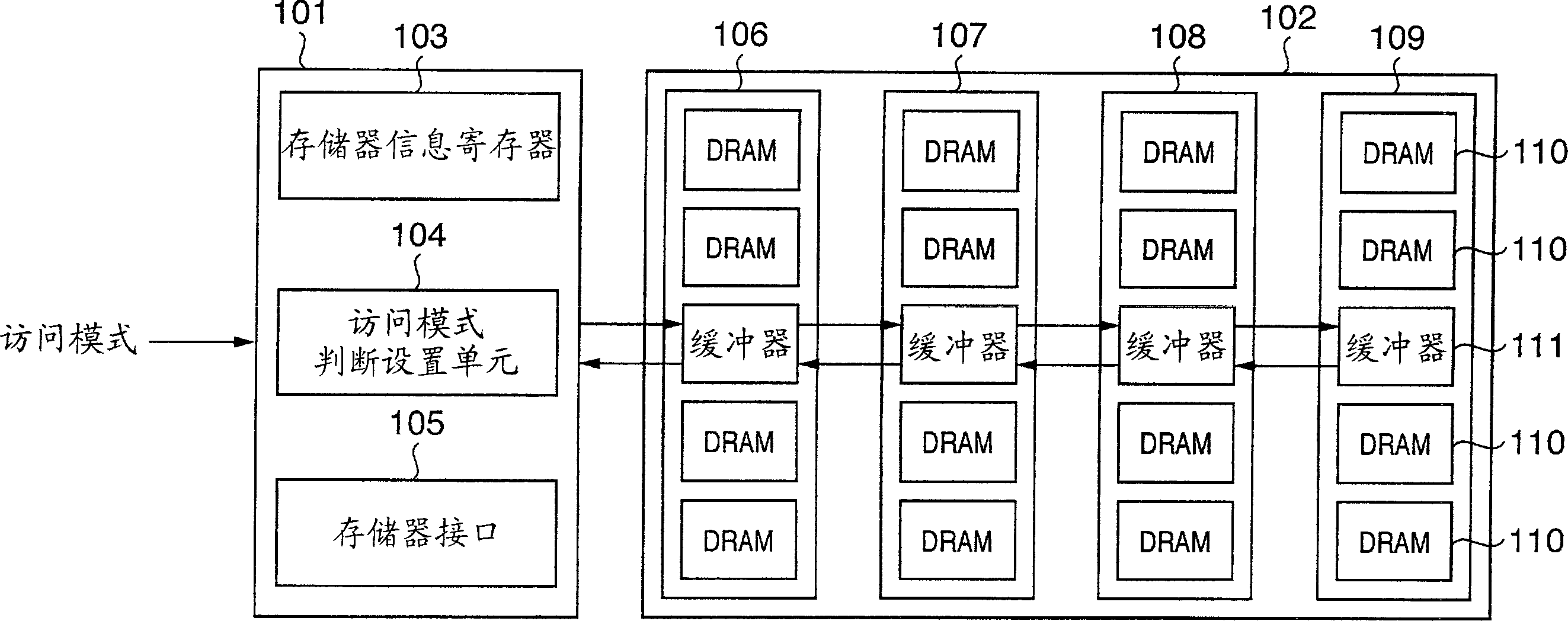
[0040] figure 1 is a view showing an example of the configuration of the storage system of the first embodiment. In the first embodiment, the memory control circuit 101 includes a memory information register 103 , an access mode judgment setting unit 104 and a memory interface 105 .

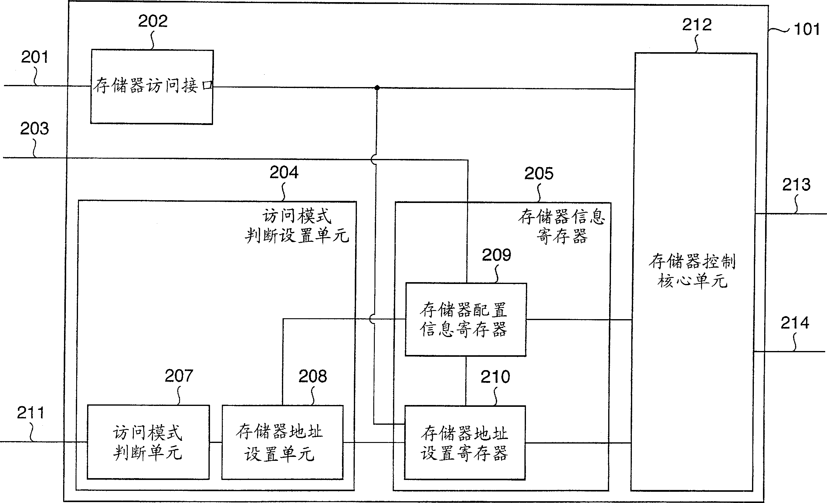
[0041] use figure 2 The configuration and control of the memory control circuit 101 of the first embodiment will be described.

[0042] figure 2 is a view showing an example of the configuration of the memory control circuit 101 of the first embodiment. exist figure 2 , reference numeral 202 denotes a memory access interface, which exchanges access commands and data with each of the memory modules 106 to 109 of the memory module unit 102 through the memory access bus 201 . Reference numeral 205 denotes a memory information register which stores an operation setting or state of each of the memory modules 106 to 109 of the memory module unit 102 through the register access bus 203 .

[00...


PUM


Abstract

Memory control device, method for changing memory addresses, and memory system. A memory control device detects memory accesses and communicates with a plurality of memory modules that are serially connected. The memory control device changes the allocation of addresses for the plurality of memory modules in accordance with the detection of memory accesses in the detection step.

Description

technical field [0001] The invention relates to an access control device, a method for changing memory addresses and a storage system. Background technique [0002] With recent advances in semiconductor technology, the internal operating frequency of processors and LSIs has been significantly increased. It is also necessary to increase the operating frequency of a memory externally connected to the LSI, especially a main memory using a DRAM, and in recent years speeding up of the memory module is progressing. [0003] In this case, it is necessary to change the structure and configuration of memory modules using DRAMs in response to this increase in speed. Traditionally, for PC 133 (SDRAM operating at 133MHz clock frequency and the standard for DIMMs plugged into this SDRAM) memory modules etc., in an unbuffered configuration (a configuration that does not connect (use) a buffer chip), even as-is There is also no problem in distributing the signals of both commands and dat...

Claims


Application Information

Patent Timeline
Patent Type & Authority Applications(China)
IPC IPC(8): G11C8/00
CPCG06F12/0215G06F12/0646
Inventor 青木恒治
Owner CANON KK
Learn More