Rotating member, housing, bearing, gearbox, rotating machine, shaft structure, and surface treatment method

A technology of rotating parts and chassis, applied in the direction of machines/engines, mechanical equipment, bearing components, etc., can solve problems such as wear and frequent

Inactive Publication Date: 2006-08-30
IHI CORP +1
View PDF3 Cites 17 Cited by
  • Summary
  • Abstract
  • Description
  • Claims
  • Application Information

AI Technical Summary

Problems solved by technology

According to the structure, the shaft part 147 can prevent the wear of the shaft part 147 due to the protection of the wear sleeve 145, but the wear sleeve 145 is worn, and the wear sleeve 145 needs to be installed and replaced.
That is to say, in order to prevent the wear of the shaft portion 147, although the entire variable stator vane can not be replaced, the problem of frequent assembly and disassembly of the wear sleeve 145 occurs.

Method used


Image

  • Rotating member, housing, bearing, gearbox, rotating machine, shaft structure, and surface treatment method
  • Rotating member, housing, bearing, gearbox, rotating machine, shaft structure, and surface treatment method
  • Rotating member, housing, bearing, gearbox, rotating machine, shaft structure, and surface treatment method

Examples


no. 1 example

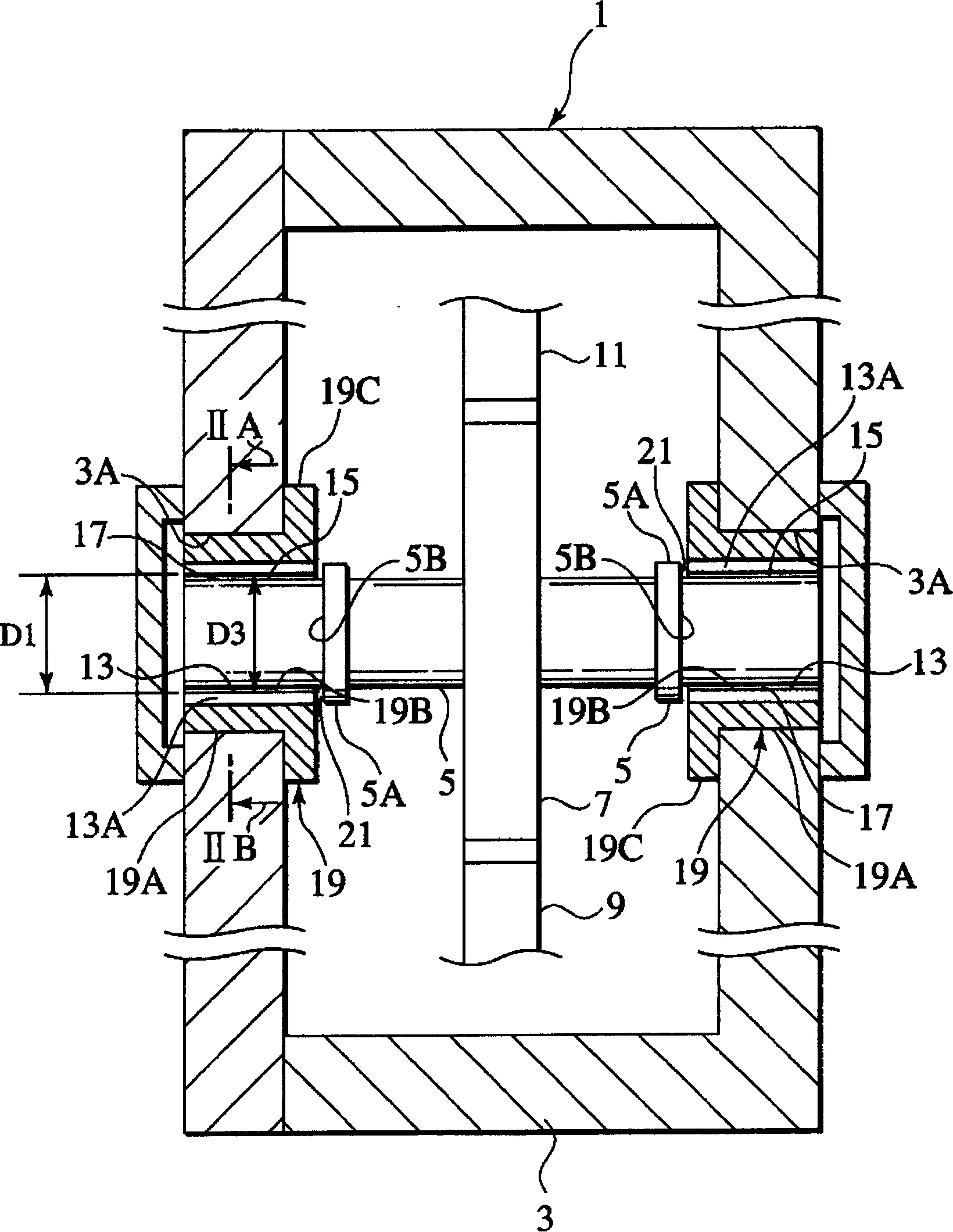
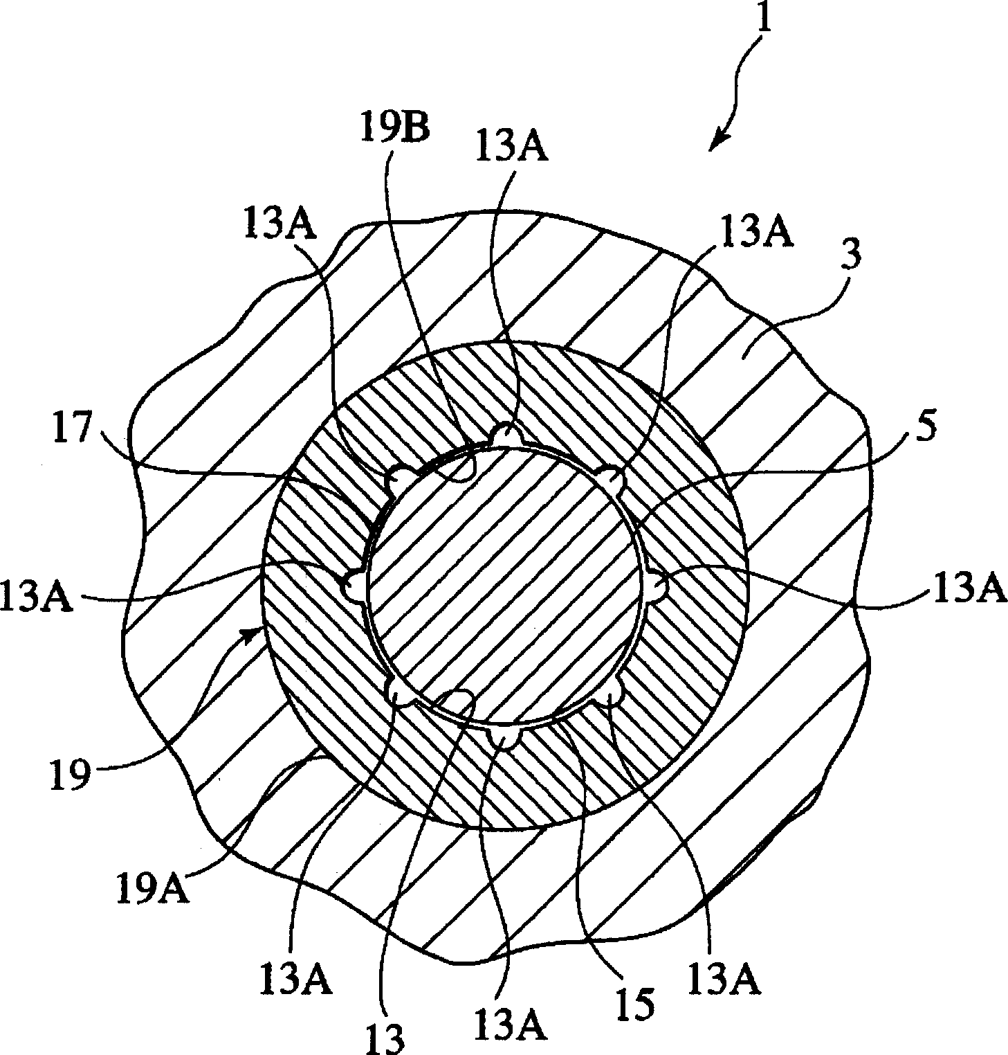
[0034] figure 1 Shown is a schematic cross-sectional view of an accessory, a driving device, and a gear box related to the first embodiment of the present invention. figure 2 shown figure 1 The IIA-IIB section view.

[0035] Parts·Driver·Gear Box (hereinafter referred to as Gear Box) 1 is a gearbox driven by the turbine shaft of the gas turbine, and is used to drive the parts (generator, hydraulic pump, etc.) of the gas turbine.

[0036] The accessory, the driving device, and the gear box 1 are provided with a case 3 supported by the engine case of the gas turbine outside the case. In addition, the engine case is formed in a cylindrical shape so as to form a compressor or a turbine gas flow path inside.

[0037] Inside the housing 3 , a conductive cylindrical rotating member 5 is provided rotatably with respect to the housing 3 . A gear 7 is integrally provided at an intermediate portion in the longitudinal direction of the rotating member 5 . Gears 9 and 11 that are r...

Embodiment 2

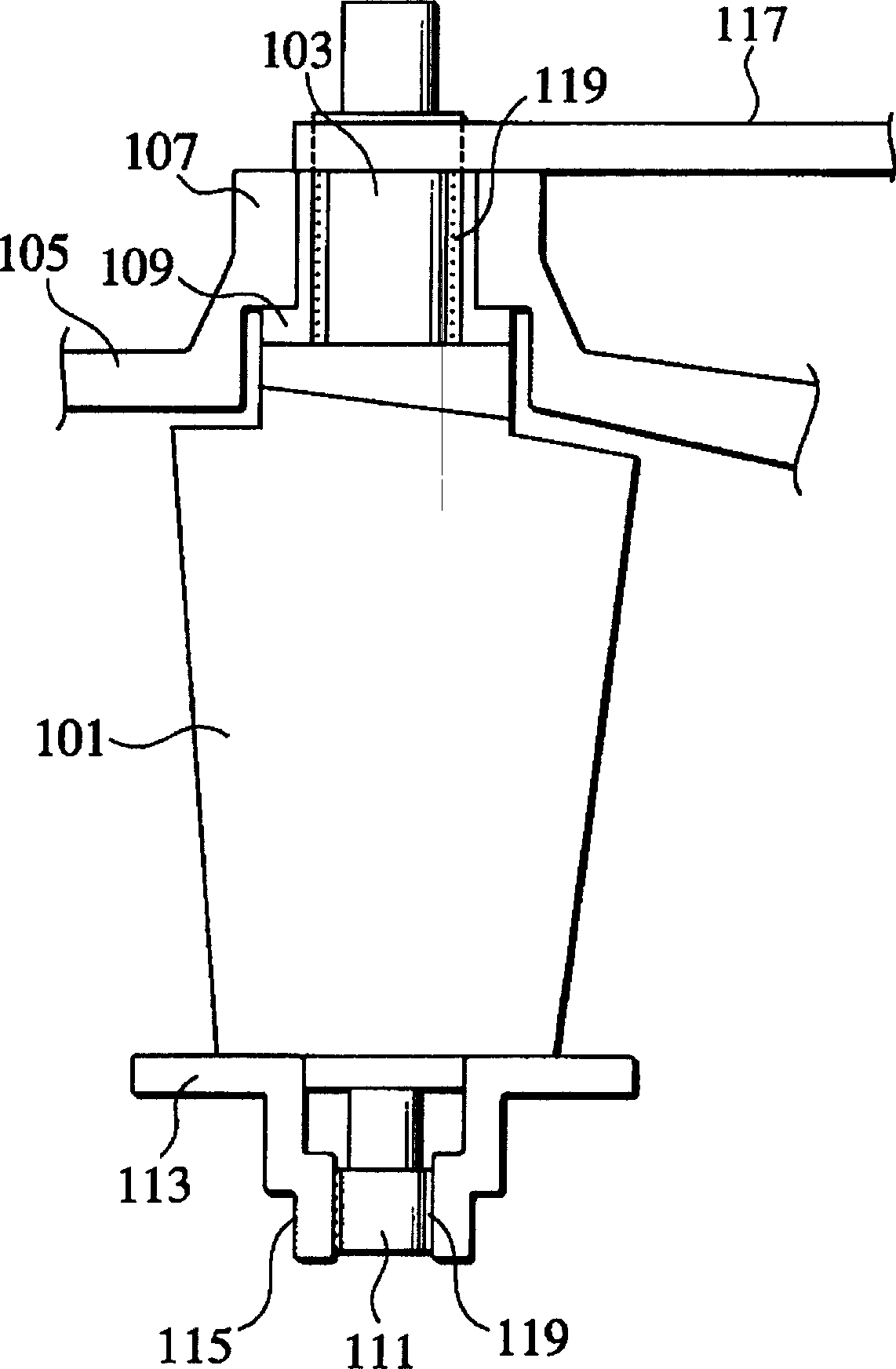
[0072] A second embodiment of the present invention, that is, a case where the present invention is implemented on a variable stator vane provided in a compressor of a gas turbine, will be described below using the drawings. In the axial flow compressor of the gas turbine, the installation angle of the inlet guide inner vane and the first few sets of stator blades is changed, so that the corresponding angle of the moving sub-blade can be adjusted to a suitable value as much as possible.

[0073] Such as image 3 As shown, the variable stator vane (variable vane) 101 that can change the installation angle is placed in the annular air flow path of the axial flow compressor of the gas turbine, in the peripheral direction between the moving sub-blade rows (not shown). at intervals ( image 3 Only one of these configurations is shown in , and the shaft portion 103 on the outer end side of the variable stator vane 101 is rotatably supported by a bushing 109 at a hole edge 107 provi...


PUM


Abstract

In a rotation member (5) rotatably engaged with a housing (3), a pulsing electric discharge is generated in a processing liquid or in a gas, between an electrode and the rotation member (5). The electrode is a chemical compound from metallic powder or metal, or a molded body formed by molding ceramic powder, or a molded body obtained by heating the molded body. Energy of the electric discharges causes coating to be formed on an engagement portion (15) engaging the housing (3), the coating formed from the material of the elctrode or a substance to which the electrode material combined by the energy of the electric discharges.

Description

technical field [0001] The present invention relates to a bearing of a rotating body, for example, at the junction of a case of a gear box and a rotating part of the gear box, a molded body formed of metal compound powder or the like is used as an electrode, and pulses are generated between the electrode and the rotating part It is related to the formation of a protective film of the electrode material at the junction by the discharge of the discharge. [0002] It is also related to the structure and surface treatment method of the shaft of the variable stator vane equipped on the compressor of the gas turbine, or the variable turbine nozzle of the turbocharger, and its surface treatment method. The shaft is equipped with a wear-resistant, lubricating coating structure and its surface treatment method. Background technique [0003] Figure 6 It is a cross-sectional view showing a schematic structure of an accessory, a driving device, and a gear box 200 . [0004] Depending...

Claims


Application Information

Patent Timeline
Patent Type & Authority Applications(China)
IPC IPC(8): F16C33/12F16C33/10F16C3/02C23C26/00C04B41/87F01D17/16
CPCY02T50/67Y02T10/144Y02T50/60
Inventor 落合宏行渡边光敏古川崇后藤昭弘秋吉雅夫
Owner IHI CORP
Why Eureka
Try Eureka